Update (26.05.2014): I’ve dug up my old build and measured the voltages of the active components.
| Q1 | Q2 | Q3 | Q4 | Q5 | Q6 | Q7 | Q8 | Q9 | |
|---|---|---|---|---|---|---|---|---|---|
| C | 8.21 | 3.48 | 8.19 | 0.48 | 6.92 | 6.92 | 6.67 | 8.20 | ~25mV |
| B | 4.13 | 1.11 | 1.13 | 1.07 | 0 | 0 | 0 | 4.13 | 0.71 |
| E | 3.48 | 0.46 | 0.48 | 0.42 | 0 | 0 | 0 | 3.51 | 0 |
| 1 | 2 | 3 | 4 | 5 | 6 | 7 | 8 | |
|---|---|---|---|---|---|---|---|---|
| IC1 | 4.13 | 4.14 | 3.95 | 0 | 3.96 | 4.14 | 4.14 | 8.20 |
| IC2 | 4.08 | 4.08 | 3.89 | 0 | 3.90 | 4.08 | 4.07 | 8.20 |
All values in Volts except where specified
V+ supply at +8.97V. All pots at 12 o’clock and the EQ section active.
I just finished this vero layout of the Diamond Compressor based on a schematic drawn by WhiteKeyHole over at freestompboxes.org. I’m not entirely sure about the EQ switch (the description on Diamond’s website states it also has a middle position) and the pot values, I’m guessing it uses general purpose diodes, and it supposedly works on pretty much any BJT which is why I went for 2N3904s. Not yet verified, but I think I’m going to give this one a try myself.
Oh, and the original unit uses a whole lot of weird valued metal film resistors, but I’m fairly sure you’ll be fine using approximate values. The parallel 820pF capacitors can most likely also be dropped.
Update (02.05.2011): Vero layout is hereby verified. Built the circuit successfully using common replacements for all the odd component values and a homemade optocoupler using an LDR and a LED encased in shrink tubing.
Update (19.06.2011): I’m reasonably pleased with how it came out in the end, but the wiring still looks a bit messy.
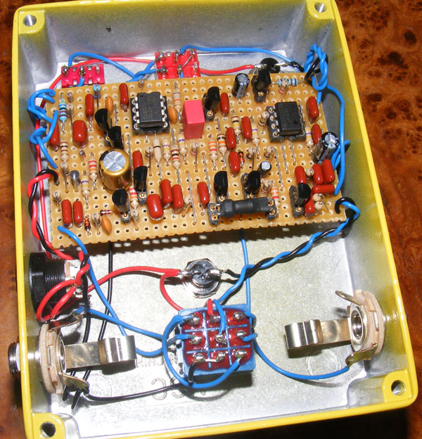
I’ve tried a different approach to the wiring on my last couple of builds. Instead of wiring everything to the hardware first and then finishing off by soldering the wire ends to the board I went the other way around. I’ve started with the wires attached to the board and then connected them to their respective offboard locations. I imagined this would be a lot more tedious and difficult, but now find this not to be the case. It also made it easier to twist wires together and keep them a bit shorter.
Update (20.10.2011): Fixed dead layout link.


I know this post is probably dead, but I thought I would just share how I figured it out. The ground for the emitter of Q9 had a cold solder joint and it wasn’t grounding correctly. I resoldered it, and now it’s working like it used to. Thanks again Harald for such an awesome website!
I don’t think the transistor is creating alternating current for the collector of my Q9 transistor. The collector and emitter are both have a reading of 8.6v, and the base is getting a reading of 9.13 volts (my power is 9.2v). Everything else is working fine, even the red effect indicator light is working, so I’m wondering why this one seems to be not functioning like it’s supposed to. I swapped it out for another one that was brand new, and I’m getting the same numbers. Could it be a failed capacitor? Any help appreciated 🙂
Hey guys, I made this pedal a couple years ago, and recently the led went out, so I tried to replace it. I got it to work, but when I put the enclosure on, something happened and the led went out again. I’m trying to trace the problem and came to Q9 with my voltmeter, B and E are both measuring around 9v and C measures 17.1mv AC. Any ideas why I’m getting those high voltages for B and E? It must be a short somewhere, but I just can’t see it. Any thoughts or guesses for help troubleshooting would be appreciated.
Typo in my last post: I meant Harald.
*bass version*
I rounded up the differences with the diamond, and lectric-fx pcb:
Q3 should be another MPSA18, Q4 should be a 2N5088, Q5/Q6/Q7 should be 2N4401, a 1M ohm resistor to ground needs added between C15-R25, IC1.1 needs to be modified to have 47.5k ohms between 2-1, 100k ohms from 2 to a 0.1u capacitor to ground (non-inverting gain of 1+ rf/ri -> 1+0.5).
I emailed the maker the differences. We’ll see what they say.
I saw this just today when looking through sites for pcbs:
http://lectric-fx.com/product/zirconia-optical-compressor-v-1-1/. I had made a bass version a few years ago using herald’s vero, and was happy to see that there was a pcb made for the diamond. I was also happy to see that the changes for the bass version were also included(and mostly correct). Q3 should be a MPSA18, Q4 should be a 2N5088.
So I was saying :
“Hi,
Thank You for this layout, it works perfectly.
Just one problem to solve : the red LED hardly lights up even with the Comp pot fully clockwise and strong attack. the bi-color led is a common anode with operating voltage 2.2V.
Is there a way to make the red led brighter ?
What about decreasing R37 value ?”
It seems that my previous post did not appear here…
Thanks! I actually saw where you answered this question a bunch of times, next time I’ll read the comments more closely. I’ve finished my build, but am in the process of isolating some weird distortion I’m getting (probably a missed solder connection, or misplaced part). excited to get this to work!
And you’re right to be confused. I am too! The layout contains the required wiring for the 3PDT, so disregard your typical true-bypass scheme, follow the instructions closely, and you should be good.
Hi,
I’m interested in making this build, but had a question about the on/off switch. Is it like the other switches (spdt or dpdt), or am I right in thinking it’s just part of the wiring for the 3pdt stompswitch? I guess I’m just confused on how to wire that part of the layout.
I don’t know how it’ll turn out, but a quick look at the datasheet for the Vactrols suggests that the VTL5C1 is quite different from the VTL5C3 when it comes to response, having opposite attack and decay.
Not promoting any specific site, but I bought mine here: http://smallbear-electronics.mybigcommerce.com/photocoupler-vactec-vtl5c3/
Thank you Harald, and what can you say about replacing VTL5C3 with VTL5C1? I couldn’t find the original component.
I wouldn’t worry too much about it and just use the 1nF.
how rationally is using 1nf capacitors instead of 820pf?
Hehe!
Gabriel, I have no clue on this matter. I say go with the LM358, and if that works you’re done!
Hi! is it imperative using a LM358A? I can only find the non-A kind in my country (Reading the datasheets I can notice some differences)
I think I will try it anyway, as the LM358 is a very low cost component, but would like your opinion on the matter 🙂
Haha! It’s usually something small like that. Very happy to hear you solved it 🙂
After going over the component placement for the 1,000,000th time I saw that the jumper on column 25 was off by a row. Moved it up and now it works like a charm! Thanks!
I don’t know enough to tell you why the signal ends at Q3 emitter, but it’s more than likely tied in with those voltages. It could be a lot of things, but most likely you have a solder bridge, off component etc somewhere that’s throwing your voltages off. I can’t remember if I’ve already said so, but do check out the debugging sections for some pointers. Are the diodes (D5, D6) oriented correctly? What kind of bias voltage do you read at the junction between R2 and R3?
Thanks so much for posting these voltages. They are obviously very different than mine. Any ideas what could be causing the variance?
I tried the audio probe again and it keeps leading me to Q3 and it goes dead at the emitter. Why would it do that?
That would be awesome if you would check those volages. This pedal really has me stumped. It’s definitely my most ambitious project yet. I would really appreciate the help! Thanks!
Some of those readings do look a bit strange, but I can’t tell you if they’re actually wrong or not. If possible I’ll break out my build tonight and make some control measurements.
Checking voltages doesn’t hurt and might be of help 😉
I had some time on my lunch break to check the transistor voltages. I haven’t had a chance to check the ICs yet.
Transistor: C B E
Q1: 9.220, 0.380, 0.176
Q2: 0.176, 0.830, 0.177
Q3: 9.230, 0.000, 0.176
Q4: 0.176, 0.192, 0.168
Q5: 6.800, 0.000, 0.000
Q6: 6.800, 0.000, 0.000
Q7: 9.220, 1.300, 0.746
Q8: 0.190, 0.660, 0.000
I poked around with an audio probe yesterday and traced the signal to Q3. I get clean audio at the base, but very sputtery and quiet at the emitter. I haven’t been doing this long enough to know if that’s normal or what.
I found the IC and transistor voltages that someone posted from this build on FSB. I’m going to check mine out today and see if they match.
So I found a few things that were wrong. The LED for the coupler was in backwards, a jumper was missing and I had a dry joint.
Now the hum is gone, but I have no sound when engaged at all. I’m going to try an audio probe tonight. Should I be checking voltages at the ICs as well?
Ah, that’s not good. After you’ve gone over everything twice and found no error, I think your best friend is going to be an audio probe (check out some info in the “debugging” section). You’ll learn a lot while tracing the schematic and layout, and hopefully you’ll pinpoint where the problem is.
I probably should have been more specific. There is no guitar signal when engaged, only the hum.
John S,
You’re right, it’s a very tricky issue to pinpoint. Apart from adhering to proper grounding rules, may I suggest as a start checking that the noise isn’t coming from the outside via your power supply? Try powering the effect with a battery; if the noise disappears you need to look at your supply filtering or maybe the power supply itself (non-regulated?). If you haven’t included battery support use some alligator clips to patch one in temporarily.
I know this is a very general issue, but I’m getting a hum when the effect is engaged. The hum gets quiet when you turn down the volume.
I’ve checked all my joints and connections. Everything looks fine. Is there any specific place I should look first?
Thanks!
I was a bit quick reading the comments. Happy you made it work, Yves! 🙂
I agree those switch pins probably shouldn’t be connected at all times. I assume you’ve looked for shorts etc.? And on/off SW 2 and p28, I can’t see why they would be connected. Again, I assume you’ve checked for shorts. Not sure what’s going on either, sorry.
Aaaaand it’s me again 😀 Finally I solved every problem. I had some issues with the dc-jack so the led wasn’t working. Now everything works 🙂 I have to hit the strings VERY hard to see the red led light, any suggestions how to let it light without destroying my guitar? 😀 Does it affect the sound when the red led lights? Thanks very much for your help and support!
Thanks Harald! Double checked it but it actually is a common anode. I made some tests with the current-tester and I found out, that pins 1, 2 and 3 (for LED-switchting) of the 3pdt-switch are electric connected independend of On or Off position of the switch. I think this isn’t like it should be. Also q31 “On/Off Switch 2” and p28 are connected, but I can’t find out how they are and if they should be. Any further suggestions? Sorry for asking that much, I just don’t understand whats going on here 🙁
Glad to hear you were able to solve it.
Double check that you’ve actually got a common anode LED. It should have three legs, which is pretty easy to check. Also, connect a battery (via a resistor of a few kohms) with the (+) terminal to the center leg; now touching one of the outer legs with the (-) terminal should produce light, while touching the other outer leg should produce a different colored light.
If that doesn’t work try switching; connect (-) terminal (and resistor) to the center leg and try to touch the outer legs with the (+) terminal. If it lights up this way you’ve got a common cathode, and not a common anode.
Hey, it’s me again.
Just wanted to tell I found the problem. There was a cut which wasn’t done properly so there was a connection on the pcb where none was needed.
The LED-issue is still not solved but can’t be that hard to find out.
Thanks all!
I looked carefully at every part of those in the EQ-section but I still cannot find the problem. I tried other capacitors for C4 and C5 and I changed a diode which seemed to be a little bit damaged. No chance.
Could maybe somebody whos build works post some voltage readings of Q1, Q2 and IC1? this would be great! Or does anybody have a link where somebody posted them?
This would be very helpful!
Thanks!
Hey and thanks for your answer! Maybe youre right withe the high-cut switch. I’ll try to fix the other problems when I find time. But c+ for LED is right, is it?
I’ll tell you when I solved the problem.
Hi Yves,
I can’t really help you with the LED and EQ switch other than to keep debugging. But I’ll comment on the High-Cut; mine is very subtle and could easily be mistaken for not doing anything. Not sure what value it is, though.
Hey all! I just built the comp, but there are some issues I can’t solve myself.
First of all: It works! The basic effect is working but the LED doesn’t light. I think I used a common anode (c+? right? ). Next problem is both switches don’t work. The EQ-Switch just turns the complete effect off. If its engaged there is no signal coming through. So the EQ-pot doesn’t work too. If it’s in Bypass ( 2&3 / 5&6 )
The High-Cut-switch just doesn’t do anything too, but it doesn’t mute the effect like with the EQ-Switch. There is just no difference in tone when switching.
Do you have any ideas what the problem could be? What could I try to better understand what the problem is?
I took some pictures and uploaded them. Hope they are good enough for you to see what the problem is: http://s924.photobucket.com/user/iefes/library/Diamond%20Comp
Thank you very very much! Hope we can get this thing running 🙂
cheers, Yves
I don’t know, but I’d guess the OP275P will be just fine. As far as the LM358AN is concerned you can probably substitute any common dual opamp (like the TL072 or the JRC4558 e.g.) but it might not sound exactly the same (or it might, who knows). You want to make sure it has a compatible pinout by reading up on the datasheets.
I’m going to build this one soon. I’m very curious about it 🙂
I’m not very familiar with IC’s so could you please tell me if there is a difference between an OP275 and an OP275P (I can get these easier) ? And are there any IC’s I can use instead of the LM358AN ?
Thank you very much! 🙂 So glad I found your page!
Thanks for the input, Abel 🙂
Ok friends, there is no need to change any of 100nF for bass mod, I checked with a meter of wave and Swicht with 100nF to 450nf. With 100nf Jump all frequencies, after investigating, the difference is that the bass comp rules with 18V ( Voltage Doubler it’s easy with 7660 ) and add “eq tilt” switch to change center of pivot from 900Hz to 250Hz: caps 4 and 5 (5n6) switch to 20nf (or experiment) and that’s it. Personally I put the pf ‘s of silver mica and the Eq section (4 and 5) oil caps from TAD , it’s a fantastic experience, this compressor is incredible, thanks Master!!!
Yeah, it sounds amazing!!! but I used Styroflex cap ‘s for 820pf, I think it will be better mkt 1nf? It is possible add attack pot? Also try a 3pdt switch to change the 3 cap’s of 100nF to 470nf, guitar mode / bass mode. Thanks, great job!!!
Ho, sorry for my English, amb from Catalonia.
Afraid I don’t know the circuit well enough to answer you, Gabriel. But maybe someone else here can shed some light on this?
Dear,
Thanks for this info. I build it and works very well, very transparent with single notes. But, when i play chords with energy, with the Comp at 1 (or more), the “intermodulation” gets high and and i hear a saturation (kind of overdrive), like not limiting the input.
Maybe it has to be with the LDR-LED Combo i chose?
The best
Gabriel.
Alright 🙂 And for the record I’ve got a section called wiring at the top of the site, which is where you’d find this and several other wiring schemes.
I figured out the wiring. I wasn’t thinking clearly but then I got it after a friend explained to me. I built it and it worked right away. Sounds great, thanks!
Could you please explain how to wire the stomp switch? This is a buffered bypass, right? I’m used to the normal true bypass. Could you list what goes to which lug on the 3PDT?
Thanks!
Thanks johnk. I’m sure someone will find this info useful 🙂
I just raised the values of the 100n’s C7, C8,& C18 to 470n’s and slightly changed the frequency cap on the tilt eq.
Looks great, johnk!
Care to share how you modified it for bass? I know I’ve seen questions on this before.
just finished mine (modded for use with a bass) and it sounds awesome! Thanks Harald for posting the vero!
hewe’s a pic of it:
http://johnkvintageguitars.homestead.com/Effects/Compressors/DCOMP-01.jpg
Both substitutes could work, but you’ll have to give it a try.
I want to use an opa2134 rather than the op275… With the LM358AN could I use any dual op amp?
Hi Gabriel. I can’t remember having either of the problems you describe with my build.
I build it, and works very good. Two considerations:
1)there is a small noise (kind of frying) in the unit, not too much, but noticible (even more with hi-gain amps). This is more evident, when you roll the EQ to the right (highs).
This is normal for this design? i know that the nature of the compressors are noisy. any comment or experience on this?
2) If you umplugg the intrument from the input, it’s start to make very nociable noise, but it’s stop when you plug the guitar. i’m wondering if that is normal for this desing.
Beside that, the compression is quite “transparent”, when you find the righ EQ, to balance the cut of highs that any compressor do. Subtle and smooth.
Glad you found the wiring. As for the LDR/LED combination I really can’t give you any helpful hints. I usually just try a few different cheap LDRs and try different color LEDs until I find one I like. If you socket both components you can swap and match easily.
Sorry, just found the wiring on the step by step page. My bad.
Thanks.
Hi, I’m attempting this build. Any particular value/spec for the LDR and LED to give decent performance for the homemade optocoupler? Does it make a difference which color LED is used for different LDRs?
Also, can you give a bit more info/diagram of how the switches and pots are wired please?
Thanks!
GX, it’s a “light dependent resistor” that you point the LED at (and wrap in black tape or shrink wrap. I got a pack with a few different sizes at Radio Shack, but everyone sells em. Here is what they look like.
http://robosense.in/images/stories/ldr.jpg
Sorry Harald, what kind of component is LDR?
A resistor?
A variable resistor?
Or what?
Thanks a lot!!!!
Yes, should be fine. Might sound a bit different though.
Hi Sabro. Can i use tl072 instead of the op275.? 🙂
Wow! this is a beast of a compressor. Hey harald, how do you like it compared to the flatline compressor? Have you tried the vactrol in the flatline? apparently a VTL5c2 is best in there, but I’d bet a 5c3 would work too…
I like the sounds I’ve heard of this, but the flatline gets great reviews when used with the vactrols… and this one is a beast of a build with a lot of spots to make mistakes in!
Anyone got an opinon? Looking for long sustain and transparent compression… I’d like the ability to get long sustain with no compression of attack as well as te ability to get some semi-deep compression of my attack.
I don’t know enough about these optocouplers to give you a good answer. I would give it a try and find out how it sounds, but it’s up to you.
Hi Harald.. 🙂 I am wondering if i can use the vtl5c2 instead of the vtl5c3. Thanks.
I’d start by making sure you have the right type of LED and that is works. Dual LEDs come with either a common cathode or a common anode, and you need a common anode one. Take a +9v battery and wire the middle leg of your LED to (+) via a resistor of, say, 10k. Now, touching either of the outer LED legs to (-) should light one side of the LED. If it’s the other way around, that you have to connect the middle leg to (-) you have the wrong kind of dual LED.
At a glance the wiring you describe seem correct.
Hope this helps a bit.
Greetings,Thanks for your layout, it’s great !!!. I have completed this compressor and it’s sounding good, but I have a problem, I can’t get the LED to work. I see in your build you used 2 individual LED’s rather that a dual color one, like the one I have. I am not sure I have wired it right, maybe you can help me…….in the footswitch, central pins, high to low, 9v+ wire from the AC input, wire from “on / off sw2” as per your layout, and wire to ground………is this correct ? I have 9V at the LED anode but it doesn’t light up……………….thanks in advance !!!
It’s an on-on DPDT. Good luck with your build 🙂
So, I’m going to start building this and your MXR Noise Gate layout in the same pedal for a friend. I know the HiCut switch is a simple On-On SPDT. Is the EQ Switch an On-On DPDT, or an On-Off-On DPDT? Thanks!
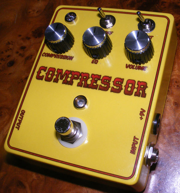
Thanks. This is an image printed to a transparent film, fastened using a spray-on transparent glue, and clear coated several times.
Looks great! How do you decorate your enclosures? Paint or something else?
I use cheap LDRs from smallbear, in this particular case I used a 9203. http://www.smallbearelec.com/Detail.bok?no=711
Greetings,
This is a nice build, I’d like to try it, however one thing still troubles me. Which value LDR did you use? I’ve seen them with various values and the layouts only say LDR. So this bugs me. Do you use the same for all builds, as I’m also planning on building the ClariNot and the modulation add-on for the Aqua Puss.
Cheers!