Here’s a vero layout for the Boss OC-2. I based this partly on a factory schematic from Boss, a modified schematic for a “chopped” version by Ben Milner and an alternative schematic (using the 4027 IC) by Stellan Lehrberg.
Update (28.05.2011): I populated an OC-2 vero board based on my layout yesterday, and it really didn’t work well. After a little debugging I realized my layout had Q1 and Q2 the wrong way. Correcting this really improved things, but there was still an issue of each pot interfering with the two others. Lehrberg’s schematic differed from Boss’ factory schematic in that he had placed 100k resistors in series with each #2 lug. This seemed to do the trick!
Update (16.08.2011): Boxed this one up tonight. What a fun and cool effect! Recommended 🙂
Update (20.10.2011): Fixed dead layout link.
Update (26.10.2011): A request for voltage readings have been made. I thought I might as well post them here for everyone:
Battery at 9.05v, all pots fully clock wise, effect on, but no signal. Battery after measurements at 8.83v.
| IC1 | IC2 | IC3 | IC4 | IC5 | |
|---|---|---|---|---|---|
| 1 | + 4.13V | +4.81V | +4.29V | +8.85V | +8.82V |
| 2 | +4.15V | +4.81V | +4.36V | +0.4mV | +0.7mV |
| 3 | +3.88V | +4.8V | +4.35V | +8.85V | +0.3mV |
| 4 | +8.95V | +0.2mV | +8.88V | +0.5mV | +0.3mV |
| 5 | +3.9V | +4.49V | +4.3V | +0.3mV | +8.82V |
| 6 | +4.14V | +4.8V | +4.3V | +0.3mV | +8.82V |
| 7 | +4.15V | +4.8V | +4.26V | +0.2mV | +8.82V |
| 8 | +4.8V | +8.9V | +7.57V | +7.53V | +0.6mV |
| 9 | +4.8V | +4.22V | +0.5mV | N/A | |
| 10 | +4.78V | +4.25V | + 2.9mV | N/A | |
| 11 | 0V | +0.4mV | +0.2mV | N/A | |
| 12 | +4.49V | +4.23V | +0.2mV | N/A | |
| 13 | +4.8V | +4.26V | +8.82V | N/A | |
| 14 | +4.8V | +2.9mV | +8.82V | +8.79V | |
| 15 | +0.6mV | ||||
| 16 | +8.8V |
| Q1 | Q2 | Q3 | |
|---|---|---|---|
| D (C) | +4.7V | +4.73V | +8.78V |
| G (B) | +0.9mV | +4.2V | +4.44V |
| S (E) | +4.73V | +4.73V | +3.8V |
I’m being liberal with the ground voltages as some of them were a few millivolts. Also pins 9-13 on IC5 fluctuated quite a bit, but neither are in use so this shouldn’t matter.
Update (08.11.2011): Corrected IC4, pin #5 reading which was a typo (9v).
Update (10.11.2011): There were obviously a couple more mistakes so I re-checked everything and updated the above voltage readings.
Update (19.02.2013): Darren reports that 2N5457 and 1N60 works well as a substitute for 2SK30A and 1N34A respectively (mind the pinout on the 2N5457).
Update (23.09.0213): Here’s the modified schematic for this layout.


Hi there and sorry for the late update!
I’m facing the same issues as Keira said 4( March, 2012 at 17:55): voltages on IC1A and a bit fuzzy sound within the clean signal. I’ve checked more than I can count…
Also verified! Great sounding pedal. Thank you very much for the layout!
hello harald
I got a problem with this circuit. Yet I have made it twice and for one and for the other, I have same problem : 4 or 5 tensions value of mine are differents of yours. Strange thing : they are pretty same of yours when I put my hand to the ground during measurement! at this moment the single bad tension I have is pin 8 ic3 (8, ic4 too) supposed to be 7,57 v. Instead of this value I got a tension which range from about 0,8 to 1,2 volts. Have you got an idea, my friend ?
hi guys
I got offset tension on the input : 1,3V! is it normal ? is it wrong ?
Hello there.
Did anyone to test it with oscilloscope? Output at oct 1 and oct 2 is strange (with generator, no guitar) and I totally can’t hear any different between clean and oct at my guitar amp. Maybe it’s working, but I don’t know if it’s correct. Lot of thanks.
Hi everyone.
Do you think its possible making the synth. Mod for the Boss OC-2 on this circuit?
Hi Harald,
I have built this one ! It works well & sounds great!
The issue I had at first was with 2SK30A replacements. I tried a pair of J105, with no luck, and after a while checking the build again & again, I noticed J112 would be more adequates substitutes (VGSoff at -5V, instead 25V for the J105 !). But again, no more improvement with the J112s until I realised the pinouts were not the same : DGS for 23SK30A but DSG for J112 (from bottom to top); The top pins of the J105 JFETs had to be reversed !
I noticed the effect is sensitive to high output basses, but with the right volume at the input the sound & tracking are great !
Thanks for the layout.
Philippe
Rodrigo,
My guess, 9/10 times there’s a short or a misplaced component/trace cut somewhere. Check out the debugging section for some pointers.
Thanks for your kind words, Will 🙂
hello harald, i’m having some weird issues, i only get effect without Q1 and Q2 (but with some weird muffled sounds).
otherwise really few effect and controls doesn’t work properly (direct level acts almost as a tone control)
voltages are almost all the same.
any idea? thanks!
Hello Harald.
I just wanted to let you know how much I appreciate your site & the the enormous body of work that you freely share. It is astonishing.
I’ve been lurking around for about 2 years now although I’ve not posted till now. I’ve learned so much from you and the other resources you linked to on your site.
I’ve studied nearly all your projects & probably built 12 to 15 of them so far.
Also, actually I’ve had many, many questions, but a little reading & I’ve always found others have inevitably asked the same questions so I’ve always been able to find my answers …. Didn’t even have to wait! hehe.
You must be some kind of saint the virtually limitless patience you exhibit when dealing with various people here.
It seems you often get asked the same few questions over and over again. I don’t know how you do it Harald but I’m very glad that you do!
Thanks so much!
Will
Hi Harald!
Thank you for the layout. Just finished it!
But there’s problem – octave signal is regularly fluctuates between octave and normal. Checked the scheme twice.
Where I have to search the cause?
It will work for guitar, certainly. Never tried it on bass so I can’t say, sorry.
Hi
will this work for guitar and bass?
Chris
On IC3, I’m only getting voltage on Pin 4 and 8, can you point me in the right direction?
Hi daniel,
If the volume is low there’s a mistake somewhere, which you should debug. Check out the debugging section.
Hi Marty,
The amplitude should be about the same as the signal going into the effect, so there’s a chance you’ve got something wired or soldered wrong. Check out the debugging section for some starting points on where to go.
Hi . sorry my english
the volume is very low , which has to be done to increase the volume?
R20 4.7uf for pop
I have one more quick question for you. The effect level is great but the output level is pretty low, is there something I could replace to increase the output. Once again thanks for the layout
Hi, Harald! I’ve built this. After few days searching mistakes it works. But I changed orientation of 2sk30, both. And it worked with orientation on your layout. Why? Okay, anyway it’s right. Thank you! http://imglink.ru/show-image.php?id=8825a4a28da655b81ba8c4ed43ed4200
Hi Jam,
Thanks for the input. You might be right, I’ll have to open up my build and see what I ended up doing there. In any case trying both ways would be the obvious way of finding out what orientation is correct. I’ll see if I need to update the layout.
Thanks for this Harald.
I am working througha build at the moment, however I noticed that the pin descriptions for Q1 and Q2 as stated on the layout pdf are wrong. I think they should be S G D from top to bottom with the transistors mounted as shown (flat edge to the right of the layout).
I confirmed this by looking at the datasheet, layout and schematic.
Sounds like it could be a problem with the pull-down resistor (R9 on the OC-2 layout). This is the resistor responsible for keeping the input capacitor at ground potential to prevent clicks and pops as you switch the effect on and off.
Harold,
First off, thank you for the layout. I recently built it and it sounds great. I am having one small issue though. I get a big pop when the effect is activated or deactivated. Could this be a switch issue or something else.
Thanks again
Kristjan,
Interesting results. Could be phase cancellation maybe, but I’m speculating. I don’t have an answer for you, but I might just have to dig out my own build and give it a try.
Hello, Harald.
I built the BOSS OC-2 veroboard according your layout. I think it works but since I actually don’t know how the real thing should sound I have a small question – actually, if anyone could give me an answer I would appreciate it. Question is – everything seems to work, direct sound is gaming thru, 1st Oct gaming thru and the 2nd Oct in gaming thru – but when I set the pots one after the other at certain level the output volume seems to be – pot by pot – gradually lower and lower. In other words – direct sound is the loudest and 2nd octave output is considerably quieter. Should it be so or am I missing something? Psychoacoustics…?
Anyway – thank you Harald for this website. I have built several of your layouts, I can’t say that I have all of them working properly right away but when I have laid them down on PCB they are fine. So, anyway – thanks again.
K
Hi Snilton,
Something is definitely wrong, but it’s hard to tell exactly what.
The voltage on the first two IC’s are a bit low. That might be because the R14/R17 voltage divider is a bit off (R14 a bit large or R17 a bit small), or it could be a result of a bigger mistake somewhere else. I’d leave these along to begin with, and look for the bigger issue around IC3/4/5.
– Did you catch that IC4 is supposed to be upside-down compared to the other ICs? Keep in mind that IC4 and IC5 are CMOS chips and can very easily be damaged. Powering one up in the wrong position could have permanently damaged the chip.
– I recommend you start looking for a mistake in a careful and systematic manner. Print out a copy of the layout and slowly go over each and every component, connection, trace cut etc. and make sure they’re all in the correct place, have the right value, and the correct polarity where applicable. Be thorough, double check everything, and cross out each part on the layout with a pen before continuing to the next.
– I have typed up a number of ideas and tips in the “debugging” section that may be helpful at this stage.
And don’t give up! You’re working on a difficult build, and getting it right is going to be hard work, but you can definitely do it 🙂
Good luck!
Oh, and you didn’t include voltage readings for the transistors, but hopefully they’ll check out.
Hi
I finished soldering this one up today and it does not seem to be working as it’s supposed to. It is dropping the octaves but the pitch fluctuates between normal and dropped. I have checked the soldering connections and cuts and so forth to no avail. Could you take a look at my voltage readings and see if you can identify whats wrong? Values here: http://snilton.com/OC2_Values.pdf
Ignore the pinout numbering on the schematic; I modified a factory schematic and didn’t update the pinouts, so they may be wrong or inconsistent.
But if you realize IC1 consists of four identical opamp sections it doesn’t really matter which one opamp is used where. They’re all interchangeable.
Hope that clarifies it a bit.
Yes i understand. But i’m in trouble with the pin connection. On schematic i Have 3 ic1 with Pins numbered 5,6,7,8…… On datasheet i See Pins numbered from 1 to 14…… Help please!
Giorgione84, you’re not seeing wrong. The schematic has four opamps labeled IC4, but this is reflected in the layout as a quad-opamp package so everything should check out.
Hi harald. Can you help me about this schematic? I See two ic1, not only one. I think this is a mistake….. Thanks
Hi Petr,
According to the datasheets I have the pinout on the BF245 is different to the 2SK30A (source and gate is swapped). Have you double checked this?
Hi Harald,
At first thanks for your work. I made this octaver recently, but I have few problems, signal is going through but it’s weak and the effect doesn’t track well and also I have aprox 26 different voltage readings at IC’s and also at transistors, I guess that there can problem with shorts or somethig, I tryed to find it, but it seems that everything is OK. Here comes the main question, I have problem to get in my country 2SK30A or 2N5457 so I found that BF245 should be good substitute and now I’m not sure if it’s ture or not, what do you thing?
I can order theese parts form abroad, but it’s quite expensive, so I tryed to make it with parts I can get in my country.
The gate voltage is too different and I don’t know if it’s given by short or cold wield (can’t find any) or bad transistor and I checked pins to put them in correct socket.
Q1 4,85V(D) 2,97V(G) 4,83V(S)
Q2 4,85V(D) 2,97V(G) 4,85V(S)
Q3 8,9V(D) 4,51V(G) 4,05V(S)
Thanks.
here’s the link for my reading, but according to the other posts I guess it’s useles
I thought I already shared it, but I see now that I’m not. Will try to find it and put it up.
Hi harald. I have a problem with the oct 2 pot and so i need the schematic for this layout. Can you share it?
Built it. Works!! Thanks for the layout!!
Hello…
I’ve been trying to operate the pedal for more than 3 weeks and as much as you do does not work…
Someone who finds it echo, has operated it without problems?
Best regards
Nice build, Jimmie 🙂
thought i’d share my build of this one, built exactly after the featured vero, all values as specefied.
https://www.youtube.com/watch?v=RgL94crOq3U
http://instagram.com/p/XUQW_TxWOE/
Hi brejna. This one gives you one and two octaves down. I’m not sure how or if it would work for bass to be honest. Have you tried searching for info on using this effect for bass?
I want to build octaver for mine friend who is bass player, so do I have to make any adaptions for bass?
Hi Rogu,
The opamp substitutes are probably fine. I haven’t encountered a CA324 before, but as long as it’s a pin-compatible quad opamp it’s probably fine. I posted voltages from my working build which you could use as a baseline, which might also tell you whether the CMOS ICs are damaged. BC548 is probably fine, but I’m not sure about the FETs; I seem to recall I had some issues getting it to work until I found the right FETs (2SK30A), bt it’s such a long time ago and I might be wrong. Start with the voltages, and have a look at the debugging section for additional tips.
Hi Harald!
My build´s not working, only Level pot is ok. Do you think the cause is the use of TL084 (Ic1), TL082 (ic2), CA324E (ic3), or any cmos ic has fail (ic4/ic5)?
I used 2n5485 with inverted SourcexGate pins, and BC548 inverted ( in my region we dont´ have 2n3904 in stock)
thanks!
Hi mehmet. If it doesn’t work then everything is -not- OK. I suggest you visit http://www.geofex.com/fxdebug/fxdebug.htm as a start.
Wish I could help you more, but there’s a language barrier here.
I’d appreciate if you share a video from youtube in your hand.
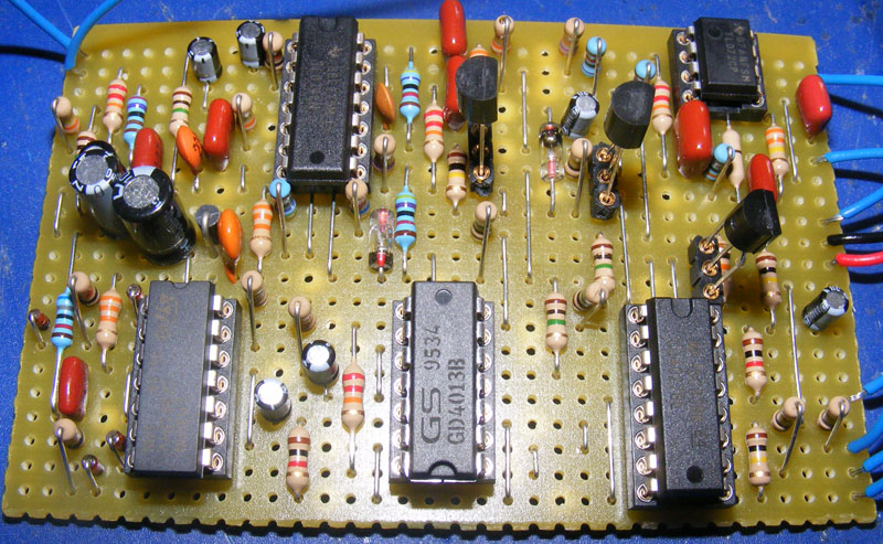
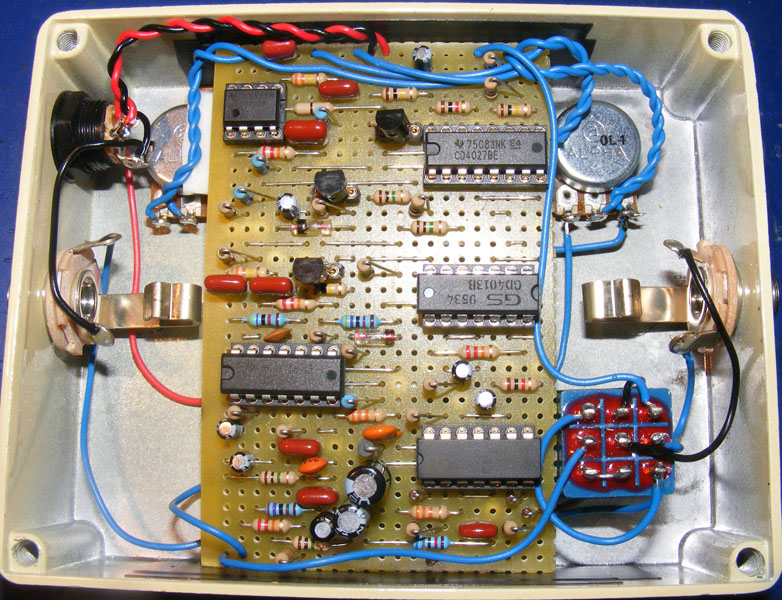
Full detailed pcb photograph
the back side and the front also sides
Integrated TL072 Seven No. Outbound Leg Tan
2.octave Potentiometer 3.nolu cord does not work
Everything is okay, but does not work
Please help me…
mehmet
Hi Harald,
I Boss OC-2 did but 2.octave potentiometer 3.nolu kablo does not work
chukker one to one the same was performed. Everything was done exactly
does not work
Please help me
Hi mehmet,
I would love to help you out but I don’t understand, sorry.
Hello
PCB circuit board OLA did, but you know, kind of a solution does not work 2.POTANSİYOMETRE BİTÜRLÜ OCTAVE ONE ONLY ONE OCTAVE SOUND WAS HELD 2ND ALL I WANT an immediate solution to the cable, NO SIGNAL …
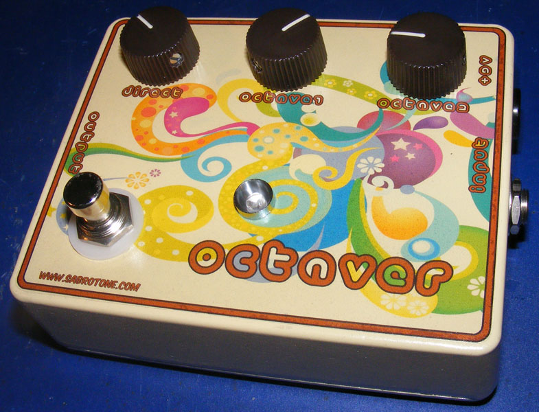
You’re going with three 100k linear pots. This info should be on the right-hand side of the layout along with a few additional off-board connections that are also required.
I’m going to build this soon but I was wondering, what value pots does it use? Thanks
Have you considered keeping this effect as close to the start of your signal chain as possible? It needs a pretty clean single note signal to track well, and most dirt boxes generate additional harmonics that could throw this off (also why chords don’t work well).
Miro I have this problem too, but I don´t know how it repair…
Built it. And it’s working, but when i hit lower notes (or use bass), it sounds like ICs are going crazy with lower frequencies. Same thing with chords. Chords i understand, but those lower notes are quite a puzzle. Did you encounter anything like this? I’ll probably check the voltages soon…
+m
my voltages are:
IC1 – #1: 1.65v #2: 1.60v #3: 1.65v #4: 8.04v #5: 1.25v #6: 1.42v #7: 1.42v #8: 4.34v #9: 4.34v #10: 4.30v #11: 0.0mv #12: 4.00v #13: 4.33v #14: 4.28v
IC2 – #1: 4.33v #2: 4.33v #3: 4.33v #4: 0.0v #5: 4.05v #6: 4.30v #7: 4.30v #8: 8.20v
IC3 – #1: 1.30v #2: 1.40v #3: 1.38v #4: 8.20v #5: 1.30v #6: 1.40v #7: 1.30v #8: 6.95v #9: 1.36v #10: 1.4v #11: 0v #12: 1.40v #13: 1.40v #14: 3mv
IC4 – #1: 0v #2: 8.04v #3: 8.16v #4: 0.0v #5: 7.9v #6: 0.0v #7: 0.0v #8: 6.7v #9: 0.0v #10: 2.9mv #11: 0.0v #12: 0.0v #13: 7.8v #14: 7.8v
IC5 – #1: 8.00v #2: 0.1mv #3: 8.02mv #4: 0.0v #5: 7.97v #6: 7.99v #7: 7.97v #8: 0.0v #9: N/A #10: N/A #11: N/A #12: N/A #13: N/A #14: 7.97v #15: 8.0mv #16: 8.02v
Q1 – D: 4.26v G: 3.79v S: 4.24v
Q2 – D: 4.24v G: 3.78v S: 4.24v
Q3 – C: 7.98v B: 4.15v E: 3.54v
Hi Harald. I have built this effect, but i have some problems.. the sound is quite fuzzy ad noisy and my voltages are totally different from yours. I’ve checked the layout four times and i didn’t find any errors =( what can i check??
Seems some of those values do match mine (e.g. IC3, #8). Did you orient IC4 correctly? Have you gone over everything with a magnifying glass and a continuity tester and made sure there’s no shorts? To be honest I haven’t got the expertise to tell what the problem is based on the voltages. Do another voltage reading just to be sure and use the diff as a guide to where you need to have a closer look.
Hi Harald,
built the OC-2 a couple of weeks ago. When activated I’m getting a signal all pots seem to work and alter the sound but it isn’t distorted/fuzzy at all and it is quite muddy. I quadrupel-checked everything, the cuts, the correct values, the wiring. It seems to be okay. I also messed with the audio probe and found some distorted sounds around the diodes D1-D4 but the distortion gets lost (I guess somewhere between IC3 to IC5, can’t locate it more precisely)
Measured the voltage and compared it to yours. The only variations I got are at:
IC1: #3 (2,24V), #5 (2,48V), #12 (4,49V)
IC2: #4 (0,01V), #5 (2,84V)
IC3: #8 (7,57V)
IC4: #2 (8,37V), #5 (8,37V), #10 (8,17V), #12 (8,69V)
IC5: #3 (8,37V)
Any help is highly appreciated. I’m really desperate with this build.
Ich! I guess I should re-check everything.
and ic 4 pin 2…and many more pins :).
Ah yes, I see what you’re referring to now. Re-checked and both pins (IC4, pin 5 & IC5, pin3) are at 0.1mV, which is logical. I guess you found a typo, thanks.
I’ll re-check for you, but those are the readings I got from my build, which to me sounds like it works perfectly.
ic 4 #5 9v and ic 5 #3 0v???
Sorry to hear that, Milan. Time to debug. Start by looking at the debugging pages at http://www.geofex.com (upper left corner).
not working for me :(…
HARALD YOU ARE THE KING!!! Thanks a lot – it helped!
Voltages posted. Good luck getting it up and running.
Hi, Pete. I’ll post IC voltages as soon as I get around to it. Hopefully soon.
Dear Harald,
thanks a lot for the layout. I built it yesterday but couldn’t make it work. Audio probed it – didn’t help. 🙁
Could you please measure the ICs in your build an post the values? That would help a lot. In fact IC4 gets very hot in my build … Any ideas?
Keep up your good work man!
Pete
It sounds almost exactly like the Boss OC-2 (you can find clips of that one on youtube). The original version has two separate sub-octaves (1st and 2nd) and a normal signal. The “chopped” version that gets mentioned now and then has the 2nd sub-octave removed and is configured for true-bypass. This layout is set up for true-bypass like the “chopped” version, but retains both sub-octaves like the original.
Sound clips are on my todo list.
Dear Sabro, a little question: how does it sound, and how about the “chopped” octave? Being italian, maybe I don’t understand how to translate “chopped” in this situation 🙂
Can i move octave up or down? I’d like to use this one to make unison bass lines with just my guitar (so I don’t need an octaver “up”)… thanks! 🙂
(and if you have a moment to make some audio samples… it’d be great!) 😀
You’re very much welcome. Good luck with your build!
Great!!! I’m going to build this one as soon as I can! I love octavers! (And I’ve requested this one some time ago, so thanks again!)