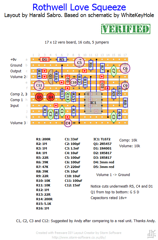
Drew a vero layout for the Love Squeeze according to the schematic by WhiteKeyHole of freestompboxes. There are a couple of unknown capacitor values, but this should be doable. Not verified this one myself.
Update (11.11.2011): Thanks to Andy for verifying the layout, and comparing with an original unit and coming up with the missing cap values!


From what I understand those letters only indicate the manufacturer and shouldn’t matter for _most_ ICs (though there are exceptions like the CD4049).
Perhaps there’s a difference between TL072P (like the original) and TL072CN I put in ?
Hello,
I made it three times yesterday with new components at each time to be sure that I made it good.
And the three ones I made distort the sound.
Did people who had this problem resolved it ?
Since you want all of the jacks on top I’d think a 1590BB would be the way to go.
This will be my first veroboard build. I would like to have the input, dc, and output jacks be on top versus having the input and output on the sides. What would be a good enclosure size for this pedal?
Hello Harald, the polariy of C10 is right. The 2 Diodes are a rectifier and C10 gets the neg. half of the Wave, so it must have its + pole to GND.
I have build the Love Squeeze and it works great. I used an OPA2134 as Opamp,and I used a 10M resistor to GND at the input. This keeps the knack away, when Hard Bypass is used.
Hi Rolf. I haven’t built this circuit myself, and have little knowledge of its internal workings, but I double checked and it is according to schematic (may be wrong of course) and I have had several positive build reports. I do agree it looks odd, though.
Hello, looking at the schematic of the Love Squeeze, I can see that C10 Plus pole is to GND. Is this correct? I think it must be turned arround!
I’ve heard others say this too. Haven’t built this one myself so I can’t really comment, but have you read the relevant threads on the forums?
Ton of distortion on this, I can hear the comp, and i like it, but It distorts, and it’s not pleasant! Help?
Great compressor. Thanks again !!
One thing to think about: As mentioned before by “Kinection”, this compressor can start to distort when volume and compressor knobs are at full. Even with my Telecaster, which has a pretty medium output… No problem for me, as the compressor has plenty volume before it starts to distort.
Is it something typical about this circuit, or did I do something wrong?
Erik.
Hi Robbie, I hope you could fix the issues and have a proper working circuit in the meantime. If not, I would propose to check for any incorrect solder bridges around the IC, which may possible have created a bypass, or even try a new IC and 2N5457 Transistor, as for instance JFETS can be prone for damage by static loads. Indeed the circuit should have distinctly more output as to what you have describe, so to me this sounds like that the active components do not work well. Maybe we could compare our voltage loadings at the IC pins (i.e. 4.85V at pin 1 & 2; 4.35V at pin 3 & 5 ; 0V at pin 4; 4.86V at pin 6 & 7; and 8.87V at pin 8) which I measured with effect on bypass, both knobs at zero and a healthy 9V battery (showing 9.11V). Furthermore, by touching pin 3 with a screwdriver the LEDs should flash up (just an optical check).
Hi Robbie. I haven’t built this one myself, but that definitely sounds wrong.
I just built this… signal passes through the circuit but the output is very quiet. Even when it’s maxed out it’s a good bit lower than the bypassed signal. I removed the transistor and leds but the signall still passed through the circuit. does that sound right? Let me know if you have any suggestions. Thanks!
You could try to attenuate the signal with a pot wired as a voltage divider on the input, but it’s not a very good/elegant solution. If all the components can handle it, maybe try running it on +18v? Afraid I’m not the best person to ask.
anyway to control input gain on this thing? it distorts with active bass (bartolini’s so theyre pretty high output)?
Hey,
Built it using this layout (only parts sub i used were 5k6 instead of 5k1, and lin pots), and i get distortion when turning the compression up (humbuckers, have not tried single coils yet).
anyone encountered a similiar problem ?
Thanks man! I have been just cant find nothin!! i just have never seen a resistor that low coming off the 9volt supply, i’m tryin to do my research first, just when i get into specifics its difficult to find my answers. I did order some books on audio electronics, hopefully i’ll get my level of understanding upped in the next few months
It’s 22ohm and it’s there to help filtering the ripple off the power supply. If this one is getting extremely hot it sounds like you have a short circuit somewhere and the 22ohm is acting as a limiting resistor, which it’s not meant for. It should not get hot. Look for solder bridges, misplaced components, a trace cut that’s missing or not properly done, or maybe some stray metal fibers shorting two tracks. Also, the continuity check on your DMM could come in handy for this.
I just built this and during testing about burned my finger off. the 22R Resistor #5 burnt up in seconds. Is it really only 22ohms? seems weird that it takes the 9v before the 100uf cap
this thing sounds great.
No idea actually, but I’d go with a linear for the compression pot and an audio one for the volume.
Hi Harald,
what about the pots?
Log, Lin,???
Interesting idea, but I’m not convinced my opinion counts for much 🙂
wow, i will be building this next, the youtube clips sound better than my keeley!
Hey Harald, you should do a post of all of your favourite pedals. you have build so many that im sure alot of people would be interested in what you think are the best sounding builds in each category!
Harald, i’m not sure the caps I used are the actual values used in the original as thats all surface mount, but it does sound very close.
Thanks, Andy. Excellent!
Made this layout, and after swapping caps, decided we needed to hear the real thing to compare, as its very transparent and not very obvious its working correctly.
A friend has one and we got it very close with the cap values I had to hand. Great sounding compressor, not at all like a Ross or Dynacomp, can only really tell it’s on when you turn it off. I prefer a Ross as its more obvious, but I can see why some people would like this one.
Here’s the cap values used, C1 33nf, C2 100pf, C3 1.5nf, C12 15nf.