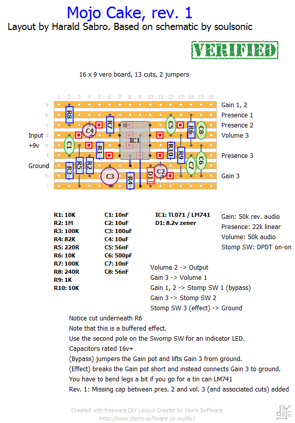
This layout is based on a Crowther Hot Cake schematic by soulsonic and is one of several apparent versions of this circuit. Let me know if you successfully build this.
Update (24.03.2012): Built this one today and had the same issue a few of you have described. There’s a 0.5-ish second delay between toggling the effect on and the effect actually kicking in. I haven’t tried figuring out why this is (I’m thinking there’s a charge-up time , but a work-around would be to hard wire the effect on and instead wire it all true-bypass. I’m reluctant to call this one verified though.
Update (25.03.2012): Good news. After reading through the relevant thread over at FSB it turns out the schematic I’ve based this layout on was missing a cap between the “Presence” and “Volume” pots and this missing cap was causing the issue I was talking about yesterday. I’ve added the missing cap to the layout and verified that it’s now working as intended 🙂


Gareth, sorry to hear you’re having trouble with this one.
First off, did you build this based on the “rev. 1” layout? There was/is a small mistake in the schematic I based this on where it was missing a capacitor between the presence and volume pot. I corrected this problem in the “rev. 1” layout. Other than that I’m not sure where to begin, but I’d start looking for bridges etc (see the debug section for tips).
Hi Harald, I’ve tried building this one and am a bit stumped. The circuit works if the gain is at minimum setting, as soon as I start turning the gain up, the signal fizzes, then cuts out. I checked the resistance of the pot and it it seems fine (50K counter-clockwise and 0 ohms clockwise). The only thing that seemed a little weird was that when I powered the circuit up and did the same measurement, I got 13K counter-clockwise and 0 ohms clockwise, is that normal? If that is how the gain pot should measure, what else could be causing this problem?
Thanks
The LM741 solved the oscillation. I really like this one although there’s still a bit decay/noise due to the IC I think. I’ve read somewhere else that this is a normal issue. Trying different ics could solve this but with all the ics I tried I had the same problem.
KT, guess I should continue on that FAQ… I meant to answer this question, but haven’t got to it yet.
thought I finally got it working. But after boxing, when I max the gain, it starts oscillating. The rest of the gain spectrum is very nice. I used the tl071 chip and have a little decay of my notes but I read on the web this often happens with this chip. LM741 is on his way.
That sucks. Hope you’re able to solve it soon. A multimeter is a good investment anyway you look at it.
desoldered pots and wires and made new solder joints. Now it doesn’t work at all except for the buffer effect. Maybe I have to buy a multimeter to check everything
Strange indeed. Have you considered a cold solder joint, broken wire or loose connection?
very strange. i haven’t changed anything but suddenly it started working, first a little bit and some time later it was working 100% (i think). Love it
I think I also have a wiring problem. I think I only got the buffer working but there’s no effect. The buffer however works great. Is it normal that from gain pot lug 3 run 3 wires? 1 from lug 3 to volume pot lug 1. Another from gainlug3 to stompsw2. And 1 wire from gainlug3 to the circuit?
Oops. Sorry about that, Wesmo. I got mixed up with another comment. I apologize.
I guess it’s just the short form way I ended up writing down these things. Ideally I would have liked to draw a wiring illustration for each layout, but that’d take away time from doing other things.
Marko?? Well, it would have been easier, for me, if it said like “then connect leg 3 from gain with leg 1 from volume” etc etc. ; )
Al
Happy to hear this, Marko 🙂
Finally got it right! : )
Sorry Harald,
but that did not help at all. I really don’t, at all, get the job done. I can’t see where what goes. My IQ must be too low, but i made one at Marks page that was easy to understand and make. I guess i have to thrash this one.
I know it can get a bit confusing, but maybe looking at the schematic makes it a bit more clear? http://freestompboxes.org/viewtopic.php?p=44956#p44956
Well, now i am confusing it: )
Let’s try again:
“Gain 3 goes to volume 1″ Gain 3 goes to stomp sw 2″
If gain 3 goes to volume 1 why isn’t it called “volume 1″ instead of “gain 3″?
This wiring, to me, is very unclear…
“Gain 3 goes to volume 1″ Gain 3 goes to stomp sw 2”
If gain 3 goes to volume 1 why isn’t it called “volume 2” instead of “gain 3”?
This wiring, to me, is very unclear…
“Gain 3 goes to volume 1″ Gain 3 goes to stomp sw 2”
If gain 3 goes to volume 2 why isn’t it called “volume 2” instead of “gain 3”?
thanks.
Consider the two poles on the DPDT stomp switch and look up how I number the lugs (illustration in the “schematics & drawings” section).
The first pole is used to turn the effect on and off, and requires three wires; lug #1 connects to “Gain 1,2”, lug #2 goes to “Gain 3” and lug #3 goes to ground.
The second pole is used for your indicator LED. Lug #4 is left unused, lug #5 goes to ground and lug #6 goes to the LED cathode (-) (and LED anoth (+) goes to +v via a resistor as usual).
That’s it.
yea, i’m also wondering how the offboard wiring goes for this one – specifically the dpdt switch, do you only hook up leads one two and three or????? trying to piece together the info here combined with the schematic and the little i’ve read about dpdt wiring. please help.
Hi, I’m just testing this one and it’s sounding really good, very dynamic and expressive with nice highs. I just have a slight problem whereby when you hit the strings hard you get a sort of crackle with the breakup. I’m guessing this is inherit with the tolerance of all the parts used but if anyone can point me in the right direction of a component I might want to adjust that would be much appreciated.
I’m using a power supply sending in about 9.6v, i think this should be fine though with the TL071.
Thanks for a great site Harold, it’s been great to have a crack at these effects and see what they sound like.
Has anyone got a wiring diagram for a buffered effect?? Having trouble working this one out!! Has this got the switch to flick between guitar / bass etc?
Hi, I’m planning to make this effect some time but does someone has already solved the problem of the half second delay? And how did you people wire it up? buffered of true bypass?
Thanks