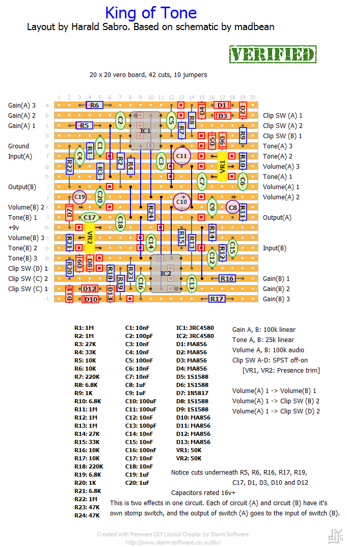
Vero layout for the Analogman King of Tone, a two-circuits-in-one overdrive. I’m really excited this layout came out perfectly squared!
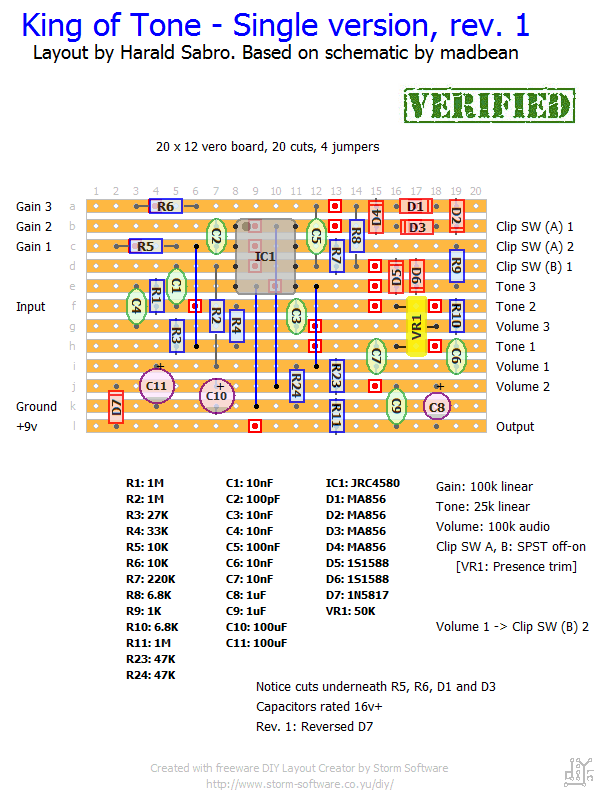
Update (25.10.2011): And here’s a layout for the single version.
Update (29.10.2011): Fixed dead picture link.
Update (12.11.2011): The full version is now verified, thanks to Glenn.
Update (23.03.2012): I built the single version tonight and found out I had D7 the wrong way. Layout revised and now verified.
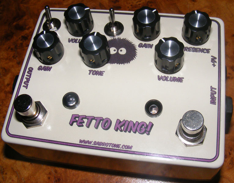
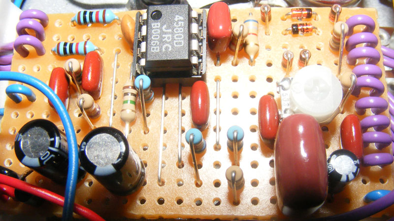
Update (19.04.2012): I ended up putting the single version of the King of Tone in a 2-in-1 box with the Fetto. The King of Tone is on the left side.
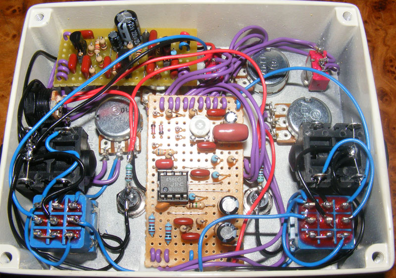
The wiring ended up being a bit too messy for my liking. Sounds good though 🙂


Hi!
Thanks for all the layouts, great work!
I have a question about the connections between Volume (A) – Volume (B) and the Clip Switch (B) and (D). This is not ground is it?
To me it would make more sense if, Volume (A) – Clip Switch (B) and Volume (B) – Clip Switch (D)…
Why are they all connected to Volume (A)?
Kindly/Mattias
Please help me with the wiring of the SPST switches. Mine has three pins underneath so which is pin 1 and pin 2?
Sorry I just noticed the notes at the bottom. Ignore my previous post
Could someone explain how the switches are wired? I understand that “Clip SW (A) 1” and “Clip SW (A) 2” are 2 terminals of a SPST, just like “Clip SW (C) 1” and “Clip SW (C) 2”, but I don’t understand where “Clip SW (B) 1” and “Clip SW (D) 1” are wired. According to the schem, “Clip SW (B) 1” should be wired to VB (is that Voltage Bias?), same as “Clip SW (D) 1” but I can’t figure out where that is on the vero board.
Any ideas?
Just saying thanks again for this layout, ultra efficient and compact, I don’t mind standing components at all. I’m still enjoying this build. Thanks for your time and effort mate!
Hey great layout thanks very much for your work on this, I’m wrestling with some pop that I can’t seem to chase away, anyone else with similar issues?
Completed the twin circuit version recently as per the layout except for substituting gain pot on one side with 250k as referred to as the ‘hot’ mod fired up first time, sounds great. Those ma56 diodes are rare but i sourced some from the Netherlands. Thanks for the layout!
Pete, based on the problem you describe I’m going to make a guess and say you have a short between pin #1 and #2. It might not be right there at the IC, but look nearby. You could also have a faulty component that has shorted, like a cap or the pot.
I’m sure you’ll find it soon 🙂
Thank you very much so far.
I built the audio probe and set it up so that I can hear the test signal and see it on a db meter as well.
Reminder: two-curcuit version – the B curcuit is generally quieter/barely amplifying.
It seems like the problem lies somewhere around IC2.
Both ICs have the same volume at pins 2 & 3 but the signal at pin 1 of IC2 does not get amplified. E.g. volume at pins 1 & 2 are exactly the same for IC2, while pin 1 of IC1 delivers an amplified signal.
Swapping the ICs didn’t change anything.
Voltages are identical for both ICs.
Where do I go from here?
If you have access to or can make an audio probe, that’s what I’d do. (check out the FAQ section for some guidance). Since you have two identical circuits, just start at input and follow the signal path until one of the circuits diverges, and you’ll be close to the problem.
I built the double version, both sides sound good but one side does not get as loud as the other one.
Voltages are identical on ICs and pots.
How do I continue my diagnosis?
This was a regular 1590BB size.
I want to build a KoT/Fetto in one box, too. What’s the enclosure size you chose?
I can’t remember exactly what I used in my build, but they may have all been 1N914’s (except D7; you can use a 1N4001 for that). Not meant to be an answer per say, but I wanted to chime in and let you know.
Did anybody come up with some good diodes for this one? I can’t seem to find any of the ones listed. I have some OA126’s and some 1N914, and 1N34’s
Thanks for the mod suggestion, Matt 🙂
…I should point out though, that this is the only high gain mod I’ve heard of; there could be more. But this is a good one!
The high gain mod simply involves substituting a 250K pot for the 100K gain pot. Since the King of tone is basically a boutique Bluesbreaker pedal as I understand it, I’ve done this in BB builds too. I built a Madbean version where I did the 100K on one side and the 250K on the other…the latter coming first in the chain. It worked out nicely, and I’ve used it on gigs several times. On these occasions I’ve used nothing but my Swart Atomic Spacetone amp, a TC Nova delay, or my Guitar PCB.com D’ay and this pedal, and I’ve heard nothing but compliments. It really covers a lot of ground! I have the 100K on most of the time, and kick in the 250K to taste.
I didn’t know about any high-gain version to be honest; in other words I have no idea. But let’s hope it’s just a few changed components and not a topology change, so we can keep using the same layout 🙂 Let us know if you find out anything about this.
…have you got any idea about the kind of IC should be used for the high gain version, Harald?
And more, do you think that for the high gain version it would be necessary some implementation on the circuit?
Hi Kris.
The full-sized King of Tone really is only two singles in series, that’s it! I.e. if you build two singles you’re there.
I was wondering if you could do a separate layout for the second half of the pedal. So you could have the single version in one enclosure. And then the rest of the full layout in a second enclosure. I’m new at this stuff and not really clever enough to figure it out myself. I run my pedals through a looper and am always moving them, and taking them on and off my board so the added flexibility would help me out. Love your website btw.
I actually solder it to the inner hole first then carefully pull it almost through the outer one (enlarged with a 1.5mm drill bit) to provide strain relief. Note that the layouts aren’t set up for this so I leave an extra strip on either side for this.
Harald, I like the way you do the wiring, specifically for the ins, outs etc., the way you push it through the outer hole from the bottom and in through the top of the next hole in. I’m guessing you allow for an extra hole on either side and make them a bit bigger so the coating on the wire fits through? Looks great!
Thanks for that info, Alan! 🙂
After a little more research, I think I answered my own question. They are just very low capacitance diodes, originally used in the VHF Tuner section of old TV’s. See here for more info http://user.eduhi.at/aquataur/aquataur/musicstuff/diode_clippers.html#The_KoT%B4s_Spice_Ingredients.
Also check out his very in-depth technical discussion on the KoT with his Tone Queen mods. http://user.eduhi.at/aquataur/aquataur/musicstuff/queen.html
Hi. I’m having problems getting the right diodes for this, especially the MA856. What’s so special about these diodes, do they just have a slightly different forward voltage compared to regular silicon diodes ? If anyone has built this, could they please measure the Vf of the diodes. Thanks. Alan
Great. Thanks for checking them for me.
Hey Harold, the pot tapers and the wiring is correct (it was me). Thanks again, Glenn
Thanks for verifying, Glenn! And I’m pretty sure the volume pot is right since it’s wired as a voltage divider and only really makes sense one way. But I’ve done mistakes before and it will surely happen again. I’ll call it verified though. Let me know if the volume pot is still wrong.
Hi, Harold, i just built the KOT (two-circuits-in-one) and it woks nice.Sounds not quite a bluesbreaker
which is what i want.Good bass and warm sounding.
I used a dip switch tree and clipping choices seem good.
I have the vero wired naked with the inputs all connected and all the outputs connected.So everything is working at the same time.
Swicthes will come later. I just wanted to prove if the circuit works.
The only thing i found suspect is either the taper or wiring lugs 1 and 3 are backwards for
the volume pot A.(from the layout, small detail)
All other pots are ok,(maybe i wired it wrong myself, I will check later but i think i did it right according to the layout)….Thanks again for amother awesome layout….hoping for the boss blues driver..hint hint.
Then I’ll be done with tube-screamer type circuits….Thanks again, Glenn