Found an interesting discussion on freestompboxes.org on the Toneczar Openhaus distortion pedal, and decided I’d have a go at making a vero layout. I plan on building this thing eventually, but the parts count is high.
Update (25.05.2010): I went over the vero layout and corrected a few mistakes. C1 and C2 were incorrectly labeled as nF and not uF, and I had the ring and tip of the expression jack switched. Will make the vero board today and start populating it. Still missing a few parts though, so this won’t be tested or verified for a while yet.
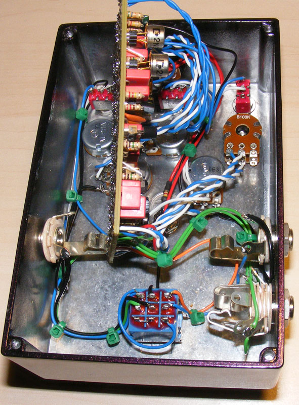
Update (24.08.2010): Populated the Openhaus vero board. Have yet to find any 2N1306 germanium transistors, but I substituted in a pair of 2N388 to ensure everything works as it should. I also had trouble finding and 470uF caps rated 25V or more that was actually able to fit physically, and decided to try a pair of 220uF, which worked nicely. The bass- and mid pots sounded like I had the wires reversed, so will have to have a look at that.
Here’s what it looks like right now:


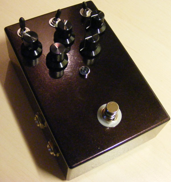
Update (07.09.2010): Here’s my completed build of the Openhaus. The only thing missing is the pair of 2N1306 germanium transistors, but the replacement transistors (2N388) does a good job for now.
Update (09.02.2011): Reversed the wiring on the Mid- and Bass pots, and updated the vero layout.
Update (20.10.2011): Fixed dead layout and picture links.


Haha 🙂 Know what you mean.
There’s no way, I’ll post a pic of the inside 😀
I wish I had chosen a 1590BB “Tall” from Mammoth 😀
http://www.flickr.com/photos/118474006@N06/12812293664/
Post some pictures when you do manage to fit it 🙂
OK, this is by far the most difficult build I’ve tried! I didn’t even believe it when it fired first time. I’m not a huge fan of high gain pedals but this one is really good! I’ve built it with suggested mods by johnk, so thanks to him for that!
And of course thank you Harald for this monster of a layout!
I have yet to figure how to cram it in a 1590BB….
Sorry, hendrix. Can’t help you there I’m afraid.
hi harald
how about Q3 and Q4 HFE ?
thanks
hendrix
well, it’s fairly noisey pedal due to it having so many gain and eq amplifier stages, but considering that it has a ton of them, to me, it’s really not too bad.
this pedal has a definite unique sound of its own and is unlike any of my other dirt pedals.
here’s a quick sound clip of mine with a p bass thru my SVT7 pro/2×15 cab:
http://soundcloud.com/johnk_10/openhaus-fingers
Hi Johnk.
Thanks for all your cool mod,,after that mod, i prefer this than my triple wreck clone (but my Build not used C20/skip part , i think the bass response too boomy with C20)) hehe
But how about noise problem (hissy) in your build?my build too noissy (hissy) when gain pots in counterclockwise position and volume at about noon (volume loud)
Thanks
Agung
just thought that i’d post a couple of pics of mine now that it’s completed (it was a tight fit in a 1590, but it DOES fit perfectly).
http://johnkvintageguitars.homestead.com/Effects/Fuzz-ODs/Openhaus/openhaus-04.jpg
http://johnkvintageguitars.homestead.com/Effects/Fuzz-ODs/Openhaus/openhaus-03.jpg
Thanks again herald for producing the vero for it!
Hi Johnk,
Thanks for all your cool mods, i will try that in my clone.
How about your gain range and noise problem (hissy) ?my build is less gainy with 2n5457 and hissy when gain pots in counterclockwise position.
sory for my bad english
Thanks
I found one more really cool mod for it. if you replace R44 (470ohm resistor) with a 1K trimpot you can adjust the frequency of the mid control’s settings. I also built a charge pump on a daughterboard so I can power it with my one spot 9V power supply without having to use a dedicated 18V supply.
Thanks for these excellent mod suggestions, johnk.
someone had previously mentioned that this pedal was a little too dark for them , and I thought so too. after experimenting with it, a super simple easy fix for that is to replace IC4’s OPA2604 with a TL072. IMO, it really brings out the top end and makes the treble control more ‘active’. in my experience the burr brown OPA chips generally are a bit darker than a standard JFet chip (like a TL072).with the TL072 i’m really happy with the pedal now.
since I use my pedals for bass, I modded mine for more low end on the bass control. it was simple. I just changed one capacitor (C29)to a 470n and it has a ton of low end now if I want it to.
good to know. i couldn’t really hear much difference in the clips of it online either. after playing thru it for a little while now, and after all that work, I think that the triple wreck is a 10X better pedal dirt pedal. IMO, the openhaus is very mid voiced and sounds like a mesa boogie to me. I wish that it had more low end and that the selectable band of the mid control’s eq was a bit wider (it’s pretty narrow).
Looks great, johnk! I think mine was also pretty subtle between the different modes.
I just finished building mine up and it worked the very first time. the mid pot as per Harald’s current vero is backwards but that was a super easy fix (I just reversed wires 1 & 3). the only thing that i’m a little concerned with on mine is its GAIN MODE switch. is it supposed to be THAT subtle? I mean, I can hear it barely making a difference but it’s almost imperceptible.
BTW, here’s a pic of my circuit board:
http://johnkvintageguitars.homestead.com/Effects/Fuzz-ODs/Openhaus/openhaus-01.jpg
found it. thanks for verifying! i did count the double one under R44 but somehow missed the obvious one under R6!
johnk,
I counted twice and got 75 cuts both times. Did you catch both cuts under R44?
i’m in process of building this one (i have everything for it, including the 2N1306’s) and the layout says ’75 cuts’, but I’ve counted them multiple times and I can only count 74 of them, so is there 74 or 75?
Posted the same question down on FSB; no reply yet.
Can someone post the voltages of his/hers original unit or the clone that sounds “right” to him/her?
Voltages on the Ge’s, the OPA’s and the lnd150n3 I mean.
I’m asking because I find my build darker and less gainy than the demos on ‘tube.
Thanks
– BS170 for the LND150? Probably not as the LND150 is a depleton mode while the BS170 is enhancement mode. I don’t know what would be a good substitute, but there’s bound to be a thread or two on the forums.
– LM7815 for the LM78L15 is ok as long as you watch the pinout and you’re able to physically fit it. Some of the regulators can be quite large, but you should be fine using a TO-92 package one.
– I like the triple wreck 🙂
Harald, thank you for your vero layouts.
Can I use BS170 instead of LND150?
Can I use LM7815 instead of LM78L15?
In your opinion which one sounds better, Wampler Triple Wreck or Toneczar Openhaus?
Thanks again.
I thank you in advance.
Hi Mr Harald,
I built this one with some replacement parts.
– 2n2369 instead of 2n1306,
– TL072 instead of OPA2604
– 2sk30AY instead of 2n5457 and its works fine, i think 2sk30 have more gain and more tight than 2n5457.. but still a bit dark (same with original OH in youtube)..
theres a mods to make this effect becomes more bright?,.and thanks for all your vero layout 🙂
I don’t know either of the devices very well, but a quick search seemed to indicate they’re at least related. If you have a datasheet for the SILND150 and you make sure you get the pinout right I don’t see any reason you shouldn’t give them a try in the circuit.
hi harald
What is the difference
between SILND150 and
LND150N3-G,. Because I
only have mosfet with marking SILND150 on the body mosfet .. is it ok?
Please help me..i want to build this monster ….thanks
Stupid me. The Gain switch 1 was soldered at the wrong place. Now everything is working perfectly. Thanks again.
I assume you’re talking about the pair of 470uF in the power section? The schematic calls for 470uF/25v here, but the caps I had at the time was physically too large so I stuck a pair of 220uF/25v in there instead. If you have the 470uF go with those. Don’t use 470nF, those are much too small.
In the latest layout I rewired a few of the pots, but can’t remember which ones. You can compare with the old one though, of course.
And lastly, it’s not normal, all three settings should produce sound. Hope you sort it out and get it working.
1st time did not make any sound, I have to trace and found 1 jumper was wrong and 2 cuts mising, plus a couple of shorted connections. Now Its working but the 470nf is correct right? you mentioned 470uf in this article. I’ve been following your earlier vero instead of the verified one, that also explains why my bass knob isn’t responding. Also, I realized 1 of the gain switch position makes the pedal silent, is that normal? Hopes no other changes between the new and old vero design.
Definitely not. I was able to source a handful of them from surplus dealer, but I can’t remember what it was called. I did initially use a pair of reasonably priced 2N388s from pedalpartsplus which worked quite well.
Anyway, here’s to hoping your build works! 🙂
Btw, got my 2N1306 from ebay and these babies aren’t cheap.
Thanks Harald…You’ve been a great help. LED is light up but I’ve no gears to test now. Hope it would work as this is 1 expensive project, now I know why the real thing costs so much.
Hi, Azz.
1. You can choose to do either. If you connect the LED to the board you don’t need any additional resistors as R18 already serves this purpose. You can also choose to to connect the LED directly to the DC jack (which should provide +18v for this effect), but you have to add a resistor somewhere in the 5k-10k range like you normally would.
2. Yes, you can get away with not using the expression jack in which case you’ll need to connect “expression tip” and “expression ring” together on the board.
I’m sorry. 1 more question. Do I still need the 2.2k resistor on the LED?
I’ve been delaying this project but now almost complete. Some things I need to ask:
1) The baypass wiring from tonepad has the led +ve going to power socket but since this is 18v I assume it goes to the LED + on the board?
2) I bought the wrong jack for the for expression. This thing still should work even though I don’t wire it up right?
I have to admit I have very little experience substituting transistors in general, and I’ve never worked with germanium ones before. I suggest visiting and searching either http://www.freestompboxes.org or http://www.diystompboxes.com for your answer.
By the way, I bought a pair of 2N388 from http://www.pedalpartsplus.com and have yet to find any 2N1306.
Hi Harald,
do you have any other suggestions for nice sounding transistors I could try in my Openhaus build? Neither I have the 2N1306 nor your suggested 2N388 – both I find pretty expensive and hard to get my hands on. Thanks in advance
Chris
Thanks a lot!
If you visit http://www.tonepad.com they have an excellent off-board wiring document in the “FX projects” category. It’ll show you how to hook up all of the common hardware with several different options depending on what hardware you’re using (3PDT, DPDT, battery snap, DC jack etc).
Good luck 🙂
Sorry for the bombardment. I get all of it already. Didn’t read the schematic properly. But it still does not show how to connect to the bypass foot switch. Hope you can help me.
I figured it out but some thing I don’t really understand. Example: Gain switch 1 & 3 are connected to the board. But I see the 2nd have wire but not connected to anything, where does it supposed to connect to?
You are right. I have not done any vero project. I have done a few mods on my pedals though, and understand how the vero board works. It helps I have electronics background. I have seen the schematics of of the openhaus vero but just don’t understand how the switches and pots are connected to the board, from the schematics.
Not sure I can help you with a better layout, sorry. This is pretty standard for a vero layout. Once you build a couple of effects you know these things.
Speaking of which, from your comment I gather you haven’t built many vero projects before? I would strongly discourage you from starting out with this thing. Get your feet wet building a few small and easy effects with one or two knobs and a low parts count first (by which time you’ll also know how to hook up the various switces and potentiometers etc). You could perhaps try a Big Muff Pi or the Merkin Fuzz, or you could visit one of the many good DIY sources in the links section looking for something appropriate.
I might do a step-by-step in the future, but I don’t have any good tutorials for you at this time. Again, you might find te answers you’re looking for in one of the DIY links on the right.
Nice.. I’d like to build 1 but don’t understand connection to the knobs and switches..DO you have a better layout?