I know very little about this effect. Let me know if the layout works out.
Update (28.12.2011): Built this one tonight just to see whether it works or not. Worked fine, so this one is verified.
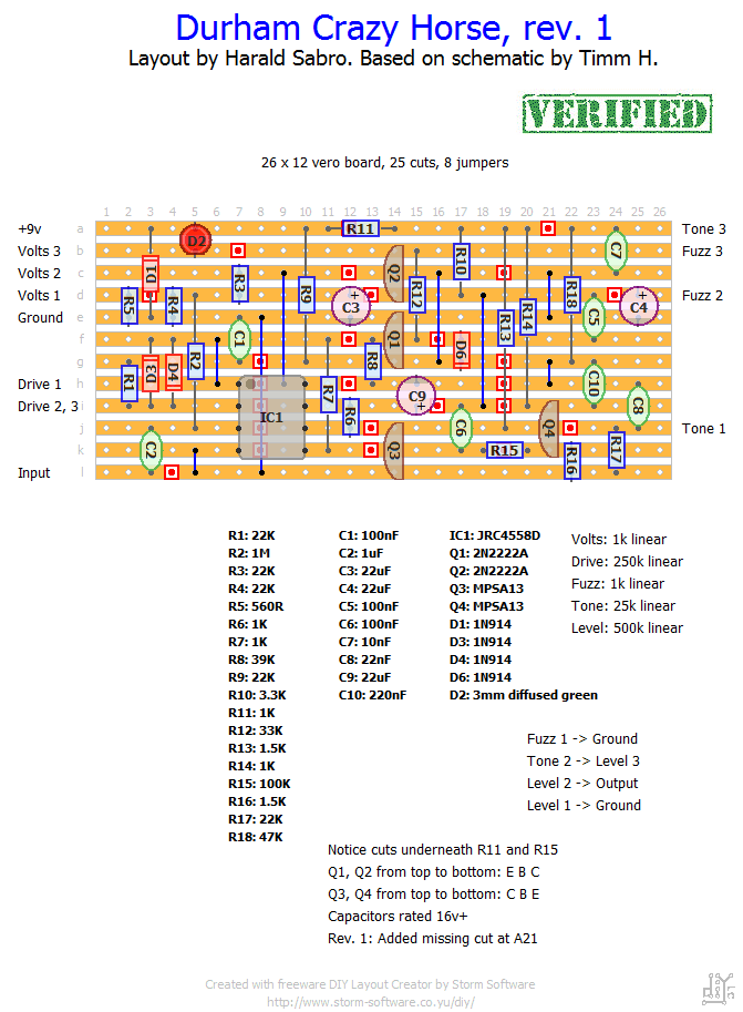
Update (04.02.2012): This is a little embarrassing (and a little puzzling) but the layout was missing a trace cut which separates the tone #3 lug from +v. No wonder some of you had trouble getting the tone pot to work. Weird thing is that I do have this cut on my build from December last year. Must have been a slip up, sorry.


You probably know more than me! If I were to guess I’d say yes, either will do fine.
Hi Harald.
I see the datasheets but don’t want to miss anything..Will MPS2222A work for the 2N2222A?
jeff
I’m not sure what’s wrong with your build, styles. I did this one tonight and it worked as advertised, including the tone and volume controls.
i’m stuck- seems like the tone control is only getting signal from the bass side, and it’s the same issue with both pedals that i’m building..anyone else have any luck with this?
i flipped q1 and q2 around and it’s much closer to sounding right now- drive, fuzz, and volt control all work as they should, tone and level are still a little screwy- i’ll keep messing with it and see what i can do…thanks!
From what I can see the tone control looks like a variant of the one you’ll find on the big muff pi. I can’t really tell you why you’re getting the results you’re describing, but I won’t rule out there being a mistake on either the schematic or the layout. You’ve double checked your wiring I assume, and also the additional wiring as described on the layout?
As for the transistors, I do try to orient them the way they’re supposed to go, but different manufacturers can have different pinouts. I oriented Q1 and Q2 according to the 2N2222A metal can variant I have at hand.
For “drive 2, 3” it’s sufficient that you wire lug #2 to the connection point of the vero, lug #3 can be left unused or bridged to lug #2 (your choice).
hello, just finished up two of these- it’ll pass a signal, but sounds a bit off and both that I built share the same issues- overall the pedals are very hissy sounding. from what i’ve read, the tone control should boost the lows turned CCW and the highs when turned CW, and be neutral at 12- a lot of the signal is cut when turned all the way CW. the level control peaks at about 9 o clock, then tapers off significantly when turned higher. not sure how to go about trouble shooting these- any suggestions?
two things i was unsure of when building- the transistor symbols on the layout are just for placement, and not orientation correct? per the notes it looks like the orientation of q1 and q2 should be flipped. also, for drive 2 and 3, is that two leads from that strip to each lug, or one lead touching both lugs?
Thanks!!
got it, thanks!
Hi, Styles. I’d definitely stick with the 2v LED and no built-in resistor. From looking at the schematic it seems to be controlling (restricting) the supply voltage to the IC in conjunction with the “volts” pot. It’s not meant as an indicator. It shouldn’t matter whether the LED is diffused or clear, what matters is the voltage drop across it.
Hi- i’m getting ready to start building this up tomorrow. I’ve got a big pile of 3mm green LEDs to choose from- does it matter what kind I use? 2v, 5v, built-in resistor, etc? Thanks!