There have been a few requests for this one. Let me know if you build it and it works. This should fit in a 1590B enclosure.
Update (11.10.2012): Revision 1; changed Q3 and Q6 to 2N5457s.
Update (22.01.2012): Revision 2; I had mistakenly labeled this as requiring 44 cuts while it only needs 43. Thanks to Nocentelli for spotting this.
Update (01.02.2012): Built this one tonight. Had to reorient the depth and rate pots (layout has been updated), but otherwise it worked like a charm.
Update (18.12.2012): Voltage readings from my build as requested:
Power supply: 8.88V
All pots fully CW.
| IC1 | IC2 | IC3 | |
|---|---|---|---|
| 1 | +3.75V | 0V | +8.88V |
| 2 | +3.75V | +3.75V | 0V |
| 3 | +3.75V | +3.70V | +7.46V |
| 4 | 0V | +7.46V | |
| 5 | +3.72V | +3.72V | |
| 6 | +3.72V | +3.72V | |
| 7 | +3.70V | +2.80V | |
| 8 | +8.88V | +3.64V | |
| 9 | +1.53V | ||
| 10 | +2.82V | ||
| 11 | ~+15mV | ||
| 12 | 0V | ||
| 13 | +1.73V | ||
| 14 | +1.73V | ||
| 15 | +0.93V | ||
| 16 | +0.93 |
| Q1 | Q2 | Q3 | Q4 | Q5 | Q6 | |
|---|---|---|---|---|---|---|
| D | +8.88V | +5.71V | +1.21V | +8.88V | +6.02V | +1.21V |
| S | +5.71V | +0.90V | +1.21V | +6.02V | +0.96V | +1.21V |
| G | +4.13V | +2.7mV | ~+4.3mV | +4.21V | +2.6mV | ~+3.8mV |
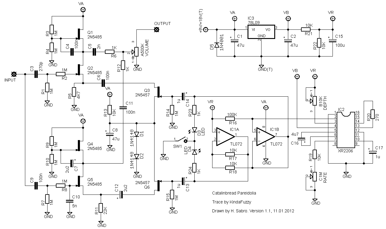
Update (30.04.2013): Just adding the schematic that I drew based on the trace made by KindaFuzzy over at FSB.


Hi Harald, great site. I just finished the Pareidolia, my first build from one of your layouts. I get signal, the pots work and the lights pulse but it seems that I have no bass frequencies coming through and low output. Any idea what could be causing this?
Thanks.
Thanks for chiming in, Dan. I’m sure a lot of people can make good use of this info. Appreciated!
Hi,
to all who think this pedal sounds trebly and hollow: I believe the value of C10 is wrong. The low pass filter will cut the sound above 32Hz, which creates a very wide notch in the pedal’s overall frequency spectrum between 32Hz and about 600Hz. Try changing C10 to something like 250pF or 270pF. Made it perfect for me. I have posted a more detailed explanation here:
http://www.freestompboxes.org/viewtopic.php?f=7&t=15124&p=244370#p244370
Dan
BTW: Thanks for a great site! Hope to be able to give something back with this post…
Sounds cool, cylens. Let us know 🙂
wow, just built it and it really sounds amazing. will post soundclips and pic when it’s boxed. one again, thank you for the layout!
as i understand it, it cycles from lowpass to hipass, really nice with bass or baritone guitar!
it fired first time, but I had made a mistake and didn’t connect Depth pot lug 1 (hey, how’s that, a pot with only one side connected?) and I had a very choppy but super interesting sound. which leads me to think I’m going to try (first time I do this) to mod it to access the different options I’ve read on the XR2206 datasheet.
Sorry to hear that, Jon. Come to think of it I built the circuit too, but never liked it enough to justify giving it an enclosure.
I figured it out. It turns out I needed to re-flow the solder on the footswitch ground.
Actually, this pedal sounds exactly like it did before I rebuilt it. Very harsh and no real depth, it doesn’t sound very good IMO… too subtle, too much high end. I think I am just going to build a repeat percussion and call it a day.
Jon. Maybe not a very helpful suggestion, but have you checked you’ve got them oriented the correct way?
Alright, this is driving me nuts.
My first attempt at this build didn’t work properly- though everything lit up nice but it was overly harsh and had no depth. I also had odd voltage readings and decided to cut a new vero board and start from scratch. In doing so I decided to de-solder all the components from the previous build and test them individually to see if I could find a faulty component and all I found was that I had an extra 1M resistor in there on one too few 10K resistors… so I figured that was the cause of my issues and the reason why I couldn’t find what was wrong at first glance.
Now the pedal is working great but the LED’s do not light up. I can’t figure out why and maybe I am having a brain fart but by all indication they SHOULD work because I get fluctuating voltage readings from 1v-4v with speed intervals that vary with the Rate pot. My first thought is that this could be a grounding issue with the footswitch… any other thoughts? (Note that I verified all components and solder points as accurate and hot)
I really want to get this puppy on my board.
Other than making sure you’ve got the correct transistors I don’t know where to start on this one, Jon. Maybe someone else here has an idea? Or you could check out the relevant threads at the forums; you might be in luck.
I have this put together, it works, sort of. It is quite harsh sounding and there is no depth to the modulation, though you can sort of hear it. The volume and rate works.
Checked my voltages and everything was in range to Harald except:
Q2 (G): .4mv
Q3 (G): 11.6mv
Q5 (G): .4mv
Q6 (G): 10.9mv
I triple checked to make sure there were no unwanted bridges, so I am guessing I have a bad component in there. I am not really great at tracing this out, though I have the schematic that I am scribbling on and I want to see if anyone here can give me hand and/or focus my eyes.
I’m crap at following schematics, but I’ll give it a shot and see what I can find out. I really appreciate the response. It does make a lot of sense. If I can manage to confirm, fix, etc., I’ll post back my findings. 🙂 Thanks again!
You’re not the first one having issues with this apparently.
Thinking about this I do believe this circuit is, in a very simplified sense, two almost identical sections, one a high-pass filter and one a low-pass filter, alternating between passing a signal. I’m guessing here, but -if- the bass part of the circuit fails to pass on its part of the signal you could end up with something sounding very trebly and well below unity gain.
My Pareidolia post should contain both the schematic and the layout; https://sabro.no/sabrotone/?p=2528. Use this to map out and look for errors in the bass-section.
I forgot one other small deviation:
I’m running this at 9v. I’m still waiting for a 78L09 voltage regulator to arrive, so instead I’ve got a 78L12 in there. I figured since I was only running it with 9v it shouldn’t make a difference since there’s nothing in the layout to pump it above 9v anyway. I don’t see how this could affect the sound, but thought I’d mention it, just in case.
Hi, all. I’m having an issue with this and was wondering if anyone could help.
I’ve built this to spec, with only the 5485s instead of 5484s as a difference. I’ve double and triple checked my resistor and capacitor values. I’ve swapped the opamp out (I only have one XR2206, so I couldn’t swap it out, but the tremoloing seems to be fine), and I’ve knifed AND filed the gaps…
The effect itself seems to be working great. Pots respond well. What’s screwing with me is that it’s incredibly Trebly, like WAY beyond Treble booster Trebly, and the volume is somewhere between 50% and 75% of my signal without the effect.
I tried Kimster’s suggestions and it’s still Trebly beyond any real use and has a significant volume drop.
Any ideas what componant in the signal path would be the likely problem?
Thanks!!!!
I haven’t tried an original so I can’t say. But I thought (as long as you use properly rated caps) you can feed the same circuit either +9V or +18V. If this is the case at least it gives you a choice on what speed to run it on.
Hi Giorgione84,
I have never tried a real one so I can’t really tell you what it’s supposed to sound like, but maybe youtube could give you an idea.
From what I recall I’ve actually heard the opposite of what you tell me now; that it sounds too bright/trebly. Have you gone over the circuit and checked that you haven’t used a component of wrong value, maybe a 100n where there should have been a 10n?
Hi, I built both a 9v and an 18v version of this one, and both work. However it seems like the doubled voltage also doubles the rate, and everything goes unusably fast. Does the original work like this? Could I just swap the C1M pot for something else or is there some other mod that would make the 18v version more usable?
hello harald. the circuit works perfectly but I have a question. the sound is very “dark” compared to clean. low-frequency output and a few high. I have done something wrong or is it a feature of the pedal?
Haha, sometimes you get lucky! I’m happy you solved it.
When it comes to the LEDs I’m not sure it’s solvable. Maybe you can try other values for R23 and R24, but this is pure guessing from my side.
Harald, you were spot on! Thanks!
I desoldered R21 and sure enough, it was 1k instead of 10k! And the worst of it is that I religiously check every component before soldering it in… I guess doing the measuring at 2am isn’t always foolproof. 🙂
The effect works great now and the IC voltages are much closer to yours. I’m considering this fixed.
BTW, is there anything I can do to make the led effect more prominent? I’ve tried all sorts of leds but while they do follow the pots’ settings, it’s more of a flickering…
GP,
Looking at your voltage readings now and it strikes me that your bias voltages are off compared to mine. I would expect most of the pins on IC1 to be at approx. half of what you see at IC3 pin 3 (regulator output), but yours are much higher. Have another look at R21/R22 and make sure they’re both 10K (measure them too, maybe one or both are way off spec.)
Here are my measurements:
https://lh5.googleusercontent.com/-I_44Lrl404w/UXwtBIp9IPI/AAAAAAAAAx4/lF3dxyV0ghE/w546-h728/IMG_2189.JPG
Q voltages are ok-ish but there’s something weird going on with IC voltages.
What kind of voltage readings do you get with those two power sources? Do they look correct compared to the ones I’ve posted?
OK, situation update…
I knifed the gaps, checked all the wiring, everything seems fine.
One observation, though. If I use an old 9V battery that puts out 8.5V as measured on IC3, the effect works as it should (supposedly) but I get horrible lfo ticking noise. If I use a chinese wallbrick that puts out 9.45V (as measured on IC3 again) I get no effect at all, just a clean signal.
Any ideas?
I didn’t do anything out of the ordinary wiringwise, maybe it’s time to do just that. 🙂
My wiring is already as short as it gets but I’ll try to give in/out/dc their own set of wires, that may help even if it does introduce more wires.
I’ll report back…
Hi GP,
Ticking noise is a common issue with most effects involving LFOs. The issue is due to the LFO sidechain signal sneaking it’s way into the audio path somehow. If you look in the FAQ section I’ve got some notes on high gain effects and squealing; the same generally applies to LFO ticking. Hope that helps.
Well, thinking about it, isn’t xr supposed to do that? Provide lfo ticking… but why would it be heard through the guitar signal? and more importantly, how do I get it cleaned up?
It’s kinda hard to follow the shortest signal path here, but I’ve found this ticking noise that gets superimposed with the guitar signal along the way.
http://snd.sc/10LinGf
It’s kinda quiet but you can hear it if you turn up your phones/speakers. I get this on Q6 and have traced it back to IC2. Faulty chip? I’ve got a 2206CP from Tayda, only one so I can’t swap it out for another one….
Excellent! I’ll look it over when I find some spare time and try to get to the bottom of this. Will report back!
Not sure what the error is, but at least I have a schematic for you: http://www.freestompboxes.org/viewtopic.php?f=7&t=15124&hilit=pareidolia&start=40#p176533
OK, there’s definitely something funky with my build.
Having examined the circuit closer up, not only do I get the ticking noise, the leds are always lit (no pulsing) and even though the circuit seems to be working fine, I’m getting some weird voltages compared to yours.
IC1
1:4.45 2:4.45 3:4.45 4:0 5:5,9 6:5.9 7:7.35 8:8.11
IC2
1:0 2:4.44 3:4.78 4:6.61 5:2.92 6:2.93 7:2.24 8:3.12
9:1.58 10:2.26 11:0 12:0 13:0.85 14:0.95 15:0.75 16:0.75
IC3
1:8.12 2:0 3:6.63
Q1 8.06 6.20 3.83
Q2 6.20 2.20 0
Q3 1.15 1.15 0
Q4 8.05 6.77 3.89
Q5 6.77 2.22 0
Q6 1.15 1.15 0
Any ideas? Do you have a schematic so that I can audioprobe the circuit?
Thanks!
Hello Harald!
I just finished my build and there’s a quite annoying ticking/clicking noise that seems to follow the rate pot. Any ideas as to what might be the cause?
FWIW, I used 2n5485s instead of 2n5484s…
Yes, that shouldn’t make a difference, MikeC.
I’d be happy to do it if it wasn’t for me salvaging my build a few weeks ago, sorry.
So far, Ive made all the cuts and soldered in all of the jumpers. I made an error with one of the cuts but I think it is ok. See what you think…..I made a cut at row L #15 right under C11, but the cut should have been at #16. However, because of the way the row is laid out, I think this mistake should be ok. Let me know what you think.
Thanks.
Hey guys!
Can anyone post a gut shot of a finished Pareidolia? I just can’t get mine to work. When I switch the pedal on i just get the clean signal with no effect.
Thanks!
I’m waiting for some Tayda parts too 😉
Thanks Harald!
That makes sense, I don’t know what I was thinking… 🙂
I’ll be building one as soon as my Tayda shipment arrives.
Hi GP,
Almost. The schematic I based this on had lug #2 coming from the circuit, the output signal taken at lug #3, and lug #1 connected to ground (only #1).
But later reports suggest it would be better to wire it in the common configuration; take the circuit signal to lug #3, take the output signal from lug #2, and ground lug #1.
Alright, I’m confused now. If I take this vero as-is, should I take the output from volume lug 3, or from lug 2 and connect lugs 1 and 3 to ground?
just finished this one harald, thought i’d share it 🙂
https://www.facebook.com/photo.php?fbid=485061991543227&set=a.240375296011899.59708.239682859414476&type=1&theater
and thanks for the vero as always!
Hi petevig!
I think you did the right thing to put lug 2 to the output. Mine behaved really strange before I changed that. Another thing I did was to tame the treble in it, it can be a little harsh. I also found that it accentuates the lower bass as well, but I kind of like it so I think it will stay that way!
Finished. Nice sound no issues. Really like the flashing LED in sync with both rate and depth, pleasant surprise, shazam!. Only used LED 1, but it appears both 1 and 2 are designed to flash. Thanks for the layout. No if you can just help me with the UMBLE.
Great! And love Steely Dan 😉
finished board with arrival of parts from Tayda. added two extra rows to left side of board to allow direct hookup of PCB type pots. put Vol 2 -> to output, and Vol 3 -> ground. used 2N5485 and v 84’s. B25k pot seems to be okay as well. heard some steely dan as soon as I strummed some chords. nice circuit, thank you for the layout. now for the case.
confirmation please. Layout shows Volume 2 at 20/L, but Kimster made changes between lugs 2 & 3 to the volume pot. should it now read Volume 3, and in the notes be Volume 2 _> Output? Had to sub and 221 for 271 at C3, and 472 for C10, and assume there is no significant performance issue. Can a B25K be used for Depth? Thanks
Maybe, but I don´t think so. After a little research it looks like it was the really early units that had this issue. Your layout is probably from a newer unit. It´s really a great pedal! And your layouts are great, thanks once again. I´m about finishing the snow white autowah right now (that´s a tight fit…), and after that it will be a baja trem…
Alright, thanks for figuring this out Kimster. Maybe this is also the fix you mentioned they do themselves?
Hi again!
I checked the layout again and I noticed one thing. The layout ays to connect the output from the circuit to lug 2 on the vol pot. I changed this to the more common wiring and soldered it to lug 3 instead and connected lug 2 to the output of the pedal. This made a huge different. I also added a 1nF cap over lug 1 and 3 to tame some of the harshness to my personal liking. Now the pedal works great and sits fine between my other pedals.
Hi! I just finished building this and it´s a fun pedal, thank´s Harald! But I noticed one thing. It´s very tricky to get the best sound out of it depending on what pedals you have before and after it. It easy gets a little bright and harsh sounding. I read that Catalinbread have made an upgrade to fix this problem and that you can send your pareidolia to them to get the fix. Anyone know what they do or how to make the pedal less tricky to put between other effects and still have a little warmer sound and don´t get so brite and harsh?
No, I don’t think you can substitute. The 78L05 will only output 5 volts which is most likely going to be inadequate for this circuit. You should probably try to find one of the +9v regulator variants (it doesn’t necessarily have to be a 78L09, but it has to be a voltage regulator in a transistor package that outputs +9v and has a compatible pinout).
Hey Harald,
Going to give this one a build – question though, could a 78L05 be used in substition for the 78L09 – in known there is slight input voltage difference, but I wouldn’t use any more than 9v on this (i see the original pedal could take up to 18v – i’m guessing why the higher 78L09). Would this change a resistor value feeding the ic?
cheers and thanks,
drsoda
Try searching for “veroboard” or “stripboard” on ebay. That’s where I get mine.
can someone tell me where to get vero big enough for this project? I can only find it 19 rows tall or from “A-S”!
Thanks! this sounds like the coolest modulation pedal ever!
anyone got any reports on how this one sounds?
the video demo sounds like it’s the most amazing tremolo ever made
My XR2206 showed up today, can’t wait to build this one!
Thank god for that, thought I was going mental. I hope to verify (or not!) as soon as the chip turns up.
I had a second look and it turns out I had placed two cuts on top of each other hence the wrong count. It’s supposed to be 43. Thanks for noticing!
Bit of help here, please. Feel like I’m going mad, I’ve counted the cuts on the layout maybe twenty times, and can only find 43 (layout says 44). Problem is, I have also counted 42 a few times, and 44 once! Can someone please confirm if it is 43 or 44? I’m paranoid about getting it wrong, as I suspect debugging will be seriously painful on such a large board.
It’s the correct ones based on the actual unit, I just failed to realize that until it was pointed out to me over at FSB.
Why the swap to 2N5457s for Q3+6? Can’t wait to build this once my chip arrives, thanks for the layout