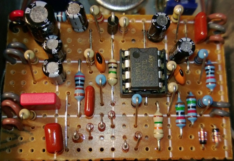
I have no idea what this sounds like. The schematic I based this on (thread at FSB) isn’t complete so I made a few assumptions. I chose not to include the last diode pair, and went with the rectifier in the power section.
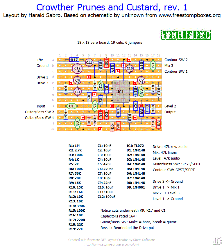
Update (07.07.2012): Reoriented the Drive pot. It should now work as advertised, thanks to Alex for verifying!
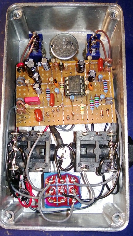
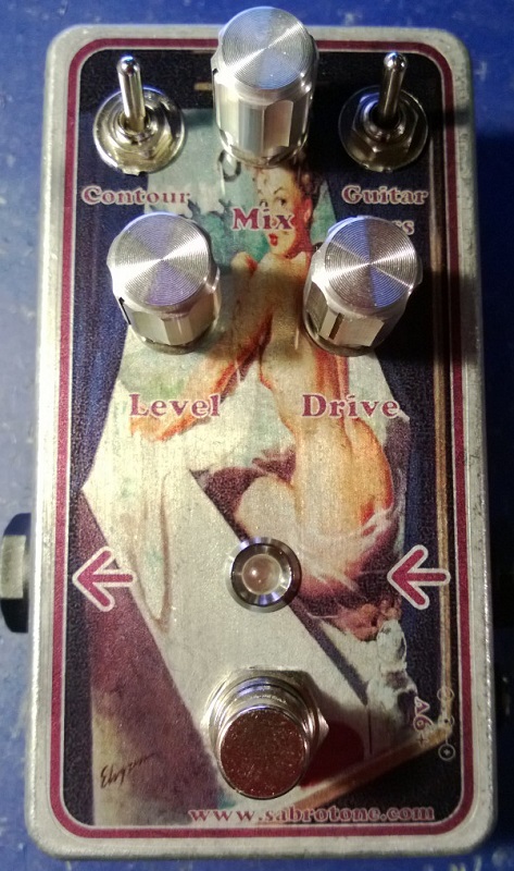
Update (12.02.2013): Thought this thing sounded great and decided to box it. Graphic is a bit on the naughty side, and I swear the input indicator was not intended!


I can’t tell what your specific problem is, but usually it comes down to a small mistake somewhere on your board or wiring. I made a “debugging” section with some guidance and tips that might help you get it solved.
Good luck, Dean 🙂
Made this a while ago.. It just sounds like a great fuzz.. There’s no filter-y sound. Any ideas of what may be the problem?
Yes, 50k pots are fine. I use those myself.
Hi Harald,
Will I be okay to use 50K pots? Having trouble getting the 47K’s from the usual source.
Thanks for your help!
Louis.
yeah, I know. I like the half mast panties on yours. 😉
Nicely executed. Doesn’t look as sassy as mine, though 😉
I built mine a while ago. It’s a great pedal for bass too!
http://johnkvintageguitars.homestead.com/Effects/Fuzz-ODs/PrunesnCustard/PrunesandCustardclone-01.jpg
Hi Tim. Not a stupid question 😉 I see you figured out the pot wiring. As for the switches you need two of them and they need only be SPST (i.e. two contact lugs; off-on), but there’s no reason you can’t use a double throw switch (SPDT). I only use the SPDT on-on ones as they are twice as versatile since they can double as SPST by leaving one of the lugs unused, and they usually cost he same.
Just saw the notes for the pots, but could still use a little clarification on the switches
Sorry for the rookie comments, but could use a little help:
On the pots, am I grounding connection 3 on the drive pot? Anything going to 1 or 2 on the mix pot? and 1 or 2 on the level pot?
And with the switched do I just ant a SPST do I want a SPST on off switch? OR a SPDT ON – ON and leave the 3rd terminal empty?
I appreciate the help
Alright. Thanks, Alex! I’ll update the layout with the drive pot reversed and call it verified. (The 2M2 resistor shouldn’t have anything to say, and I’m not really sure it’s necessary given the 1M vref resistor following the input cap but doesn’t hurt).
This is what it is supposed to sound like:
http://www.youtube.com/watch?v=uwkrcZtTgLQ
That’s what I did following the FSB’s pcb version and it now works.
Just reverse the Drive pot.
Does the extra 2.2M resistor I’ve mentioned before make any difference?
I’m not very good with the theory!
Thanks
Thanks for the feedback. So you’re saying the drive pot need only to be reversed?
Hi Harald,
I’ve built the Crowther Prunes & Custard and it wasn’t working at first.
I’ve checked a pcb version on FSB and, although the schematic said the opposite, I’ve inverted Drive 1 and Drive 3 connections (Drive 3 is now grounded), added a 2.2M resistor between input and ground (not sure if that makes an actual difference!) and it now works!
Hope this helps.
Thanks for your great website!
Alex