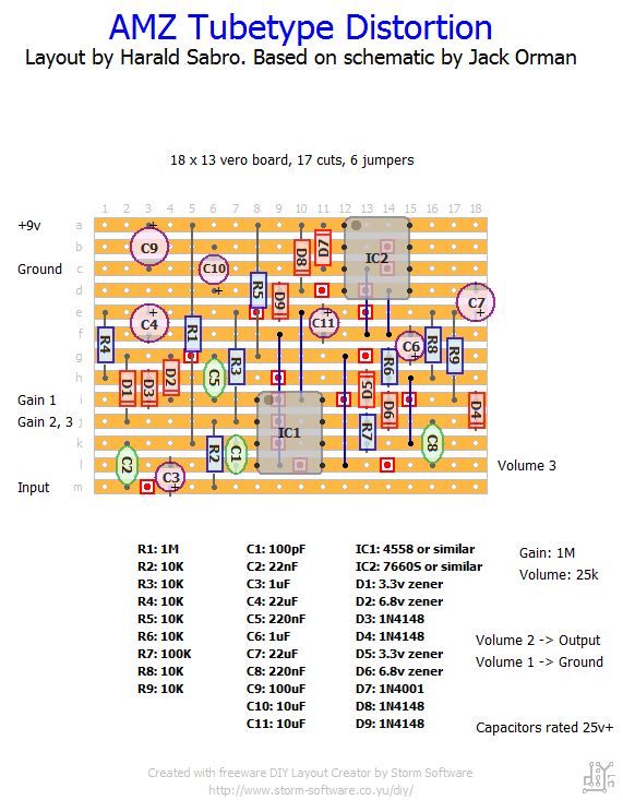
Found a small article on AMZ about some patented tube emulation circuit used in Crate amps. Jack Orman put together a simple effect schematic based on the patent information and I’m keen to find out what it sounds like.
The effect calls for +18v to work properly so I put in a standard voltage doubler. I’m curious about this one so I’m definitely going to build it (eventually), but let me know what you think if you decide to build it too.


Thanks for the tip, damien. Will look it up!
Type “vh140c schematic” in google, and you’ll get the good two stages inverters op amp distortion. Each inverter distord one side of the signal. Channel A is high gain from 4 vpp to 10vpp clipping and, channel B low gain. AMZ booster came to something far from the original patent…It need a lot of eq after like all distortion, but it’s awesome. No need of >5 stage fet tweaking to produce high gain distortion, 2 stage op amp do the trick pretty well ! And more gain should be added by changing the gain pot value…
Thanks for the feedback, Tazidore. I’m having a similar experience with my build, just wondering if it’s me, the layout or the design.
Hi !
First of all : Many thanks for sharing your incredible work !
Built this AMZ tube type exactly as drawn, fired it up on first plug, nicely aggressive, but kind of fuzzy/farty, with gated sustain. Not worth keeping …
Anyway, these parts will end up in another one, so it does’nt matter.
Wish tou the best !
Hi Benno. Hmm, sounds like something’s wrong alright. I did add a charge pump to provide the +18v internally which accounts for the two missing resistors (they were used as a voltage divider). I’ll eventually try to build this one myself, but until then I can offer little advice I’m afraid. Sorry.
Hi Harald, I’m getting a really fat fuzz sound from this, which when playing single notes it sort of cuts out like a voltage sag. So I believe something is wrong. I’ve got 18v at pin 8, though. Any ideas? Much appreciated thanks. The schem has 11 resistors, while the layout has 9, if that could be an issue. Thanks mate