This one was requested a long time ago. Here’s an overdrive pedal that uses an actual preamp tube, which is quite exciting.
Based on Bajaman’s schematic I created a layout with wiring for the tube pins (since I can’t imagine a tube socket fitting neatly on a piece of vero board). I left as much space as I felt was necessary for the large supply caps, but I’m afraid it could still end up being a bit crowded. The effect uses a preamp tube of type ECC83 / 12AX7, and I guess you would need some ventilation in your enclosure. The wiring explanation is a bit convoluted as well, sorry. I really should draw a proper diagram for this.
Do note that this effect requires 12v AC power and not DC like most other effects. Use a small mains transformer or a good 12v AC power supply, and be careful when playing with mains power. Don’t do it if you’re not sure how to do it safely.
Update (09.09.2012): Thanks to several of you for verifying this one!
There’s also been reports of this being quite noisy, and I’m happy to pass on coi2001’s suggested fix; leave the heater resistor off the board since that’s the main noise source. Run the 10 ohm resistor (R16) from the 12VAC source (probably a trafo in most cases) straight to the heaters.
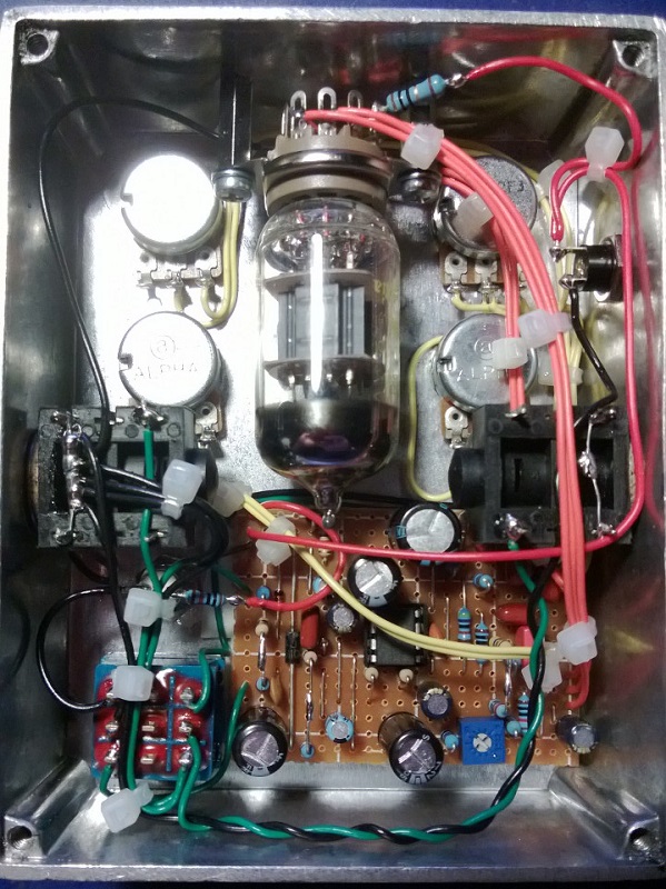
Update (09.05.2013): Here’s my own build, in a slightly taller 1590BB enclosure I got from smallbear (I think they call it the 125BB) which gave just enough room for the tube. Left the heater resistor off the vero board, as was previously suggested, and set it up to receive 12VAC external power (no room for a transformer and power socket obviously).
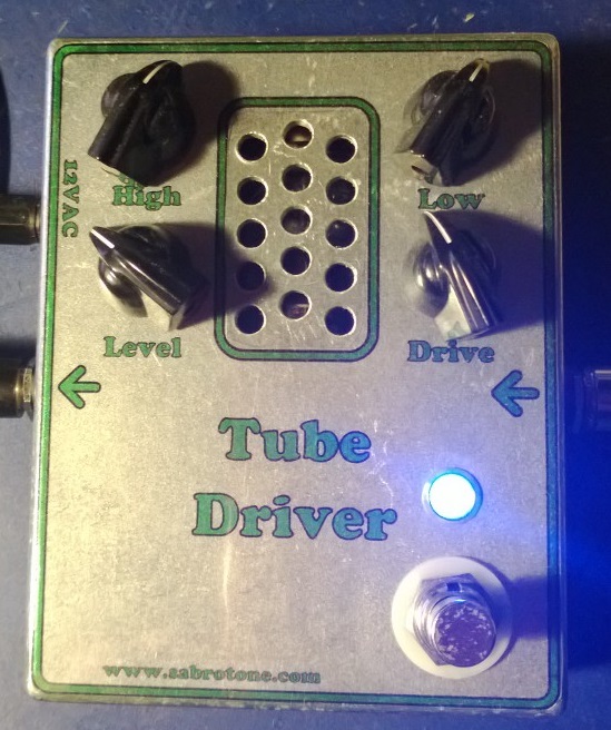
Sounds great and there’s very little hum, just a small amount when drive is full on! 🙂


Thank you so much for this wonderful layout it’s been a while ii want to built this, For power supply what type of transformer you have used 12v-0 ac and does it need mA rate.and what did you used for yours,
Thanks
I d love to see a vero for a fet conversion of the tube driver but cannot seem to find one anywhere! Any ideas, Harald? Thanks in advance!
Hmm it would be lovely to just have a simple and clear wiring diagram, that covers ALL of the comments, modifications and implicit connections not mentioned on the original overboard diagram. Can thus simply be done, to save from headaches, uncertainty, and total melt downs?
It’s been such a long time, but I do think a 1/2W resistor is a good idea.
Hi!
I just completed the pedal and tried to power it on and immediately the R16 (10ohm) went up in smoke!!It was 1/4 watt.Do i need 1/2 watt or is it something else?Do i need to make all the resistors 1/2w?
Please help!
For anyone having issues with the pedal having to much HIGH frequency’s.
Try adding a 2nF cap between LEVEL 3 and GROUND. (works great)
Any thoughts on how to eliminate teh 50/60HZ hum?
I have shielded all signal cables which helped alot, but there is still a noticable amount of hum.
Adding filters to the Powersupply part of the schematic does not seem to work…
PS i built the GeneralGuitarGadgets version.
Benoit,
You’re going to need a 9v AC supply. The bipolar voltage converter you are referring to is most likely DC (hence the name bipolar).
Hi guys!
Do you think that it can work with ~17v AC (Bipolar voltage converter from IvIark)?
Thanks!
Check out the FAQ section, Alex. Following some guidelines for high-gain effects may be the cure.
I tried to build this one and get high pitch noise. Like the scheme has self-oscillations. Have anybody had something like this.
btw, here’s a quick sound clip of mine with a p bass:
http://soundcloud.com/johnk_10/bluetube903-wav
thanks! I got the hum issue pretty quiet (and acceptable with a 12VAC wall wart), but it’s now absolutely hum free with a 12VDC wall wart using the ICL7660S for a +12 and -12V bipolar supply for the chip and 12VDC on the tube filament. with the 7660S, i’m sure that it all could be on one vero, but since I separated mine for the AC filter, I didn’t want to have to make a third one. 😉
Nice work, johnk 🙂
well, I ended up making my own vero for this one and it works perfect, sounds great and it’s very quiet now. for the noise/hum issue, the trick is to make a separate board for the filtering. I made the 903 which has the mid control and also made it true bypass.
I still might get my first one out and make a separate filter board for it’s power supply, but my second one works so good, it’ll be a while before I do that. here’s a pic of my new one:
http://johnkvintageguitars.homestead.com/Effects/Fuzz-ODs/BKButler/903-02.jpg
….and here’s my vero layout for it:
http://johnkvintageguitars.homestead.com/Effects/Fuzz-ODs/BKButler/01-903BLUETubeDriver.png
I’m sorry it’s not going well, Johnk. Unfortunately I haven’t built this one myself so I can’t really share any insights (I have it on my todo-list though). Keeping fingers crossed for you.
I’ve tried everything (star grounding, non board mount resistor for the filament, twisted leads with a dedicated ground from tube socket etc.) to remove the hum when the dirt is engaged but to no avail. I also have a realtube BK butler driver here to compare my build to, and it is silent. it also has a lot different tone than my build (the original one has way more low end, whereas the vero kinda sounds ‘middy’ like a tubescreamer. the last thing that i’m going to try is to make a new vero layout with the power supply ona separate vero. if that doesn’t do it, i’ll also try using two regulators in it for the DC to power the chip. if that doesn’t do it, I give up and it’s going in the bin. That said, I’ve built 8 other Sabro layouts and they all worked perfect upon the first powerup and all of them sound great, including the Philosopher’s Tone which is a pretty complicated build.
TJ, rather than me explaining it wrong you should read up on how to safely wire a mains transformer. And do make sure you understand it; safety first. It’s also a good idea to use a bulb limiter when you first try to power everything up.
Here’s a few quick links that could give you a good start (google search for mains transformer wiring):
http://www.diyaudio.com/forums/power-supplies/170261-transformer-wiring-mains.html
http://www.e-dan.co.uk/electronics/wiringtrans.html
http://sound.westhost.com/psu-wiring.htm
http://sound.westhost.com/articles/power-supplies2.htm
http://www.mhennessy2.f9.co.uk/articles/power_supplies.htm
http://valvewizard2.webs.com/Transformers.pdf
Wow, thanks for the quick reply! 🙂
So grounding is basicly just the second transformer lead to the enclosure and both input and output jacks share it? Isn’t there gonna be a (don’t know the exact word for it; short circuit?) if the current flows from an AC lead to the safety ground pin from the mains?
By the way, thanks for the site and its layouts and schematics. I’ve already built 2 of the effects with your layouts 🙂
Hi TJ, utmost care when working with mains, of course.
You’re not taking ground directly off the mains connection, but rather from the secondary side of the transformer. Note that if you have a three connector mains socket you do want to securely attach the safety ground connection to the metal enclosure close.
You want the neutral and live connections from mains, via a fuse, straight to the primary side of your transformer. Then you designate one side of the secondary as ground and the other as your 12VAC, and these two are the ones you use throughout the rest of the circuit. This is part of the reason you have a transformer to begin with; it provides some isolation and security.
Wish I had a good source I could refer you to. Make sure you understand how this all works so you avoid any dangerous situations. Good luck 🙂
Hi!
I am going to attempt to build this one as my first tube-involving project. But I have a question about grounding: I am guessing that the enclosure is grounded to the mains ground pin. So how about the transformer – is the “ground” lead connected to the enclosure or should it be just floating around and connecting “ground” points in the circuit? And the jacks – are they to be grounded with the enclosure or the transformer “ground” lead?
Thank you for your time,
TJ
Hope you get the hum sorted, Benno!
OK, thanks mate.Cheers for that. Apart from the hum it sounds fantastic. By the way Harald, the layout is great, the spacing between the big electros is fine. Thanks again.
Maybe you may want post your question on the diystompbox site so you can attach pictures and get help
Its the ground from the transformer( Im assuming), the centre tap on it says 6.3v.I chopped that one off! I also tried connecting to a 12VAC plug pack instead but still get the same hum. Thanks for your help.
What is transformer 0 volts.? A center tap? If so you do not need to use it.
Thanks Costantino. I’ve wired it like this.Splitting the two outputs of the transformer.
Transformer- 12.6VAC—>10R->tube pin 4
Transformer -12.6VAC—>Vero
Transformer- 0V->tube pin 5
Transformer- 0V->Input Jack( Ring).
Input Jack( Sleeve)->All other Grounds.
Does that look correct? Does the transformer and tube socket need to be isolated from the chassis? Sorry about all the questions,appreciate the help
Benno: yes I have done that to make it easier to fit it in a 125BB box. I have built other versions of this effect with the power supply on the same board as in Harald’s excellent layout, and the hum was minimal , as long as the filament was powered directly from the transformer.
C
Oh yes, that would make sense. Thanks again Harald. Up and running now, sounds good, but I do have a deep buzz with the effect ON. Reading Coi2001’s post, has he removed all components relating to the supply to separate vero perhaps?
Hi Benno.
The tube glowing means you’ve got the heater up and running (pins 4 and 5, and technically also 9,but we’re not using that). This is required for the tube to operate properly, but you still need to provide the rest of the circuit, including some of the other tube pins, with power. This is done by connecting the “12VAC” and “Ground” points on the cicuit board.
With 12VAC supplied direct to pin4 of the valve via 10R, does an additional power connection have to be made somewhere to the rest of the circuit on the vero.? I ask because the valve is glowing, though I have no signal with effect on, and both LEDs(power + indicator) don’t work. Am I missing something obvious? Thanks
Thanks for that, I’m going to try with a small mains transformer first.
No jumper. I was probably a bit unclear there. You want the heater filament (between pins 4 and 5) and a 10ohm resistor in series between the 12VAC and ground, so 12VAC to 10ohm to pin4, then pin 5 to ground.
I suppose your PSU has to be unregulated since it’s AC. The regulation plays a part in making a DC rectified AC signal “perfectly DC” after having first filtered it.
Hi Harald. A couple of questions. Where 12VAC-10r-ecc83(4)-ecc83(5)-GND, is a jumper to be soldered between ecc83(4) and ecc83(5)? Also can I use a 12VAC unregulated PSU.? Thanks mate
Thanks for this very useful tip, coi2001! I’m adding it to the layout.
Working and boxed, has become my favorite overdrive.
As pointed out in several forums, the hum problem has to do with the AC used for the tube heaters. To get rid of the hum I hooked up the heaters (pin 4 and 5), and the resistor to step down the AC voltage to 12.6V, directly to the output of the power transformer, not the board. To facilitate boxing (125-BB size from Small Bear), I split the power supply from Harald’s layout and made a separate vero. Now there is no hum.
Harald, this is another great gift to the DIY stompbox community.
Thanks again
Costantino
Disappointing 🙁
I also tried shielding the grid leads, no improvement
Costantino
Harald: thank you for your reply. I tried shielding the input/output (as suggested at freestompbox), but is did not help. Looking at other forums, hum is not uncommon for this effect, especially the GGG layout. I was thinking whether placing the power supply components on a separate board might help or arranging the components as in the original Butler layout.
Nevertheless, this is a great effect and we thank you for it!
Costantino
Happy the layout itself works, but maybe this is the kind of effect that doesn’t really work on vero? Having the tube socket off-board might cause some noise problems because of the excess wiring, but I’m just thinking out loud here.
Built and working, but like in Mark L.’s build, there is buzzing. Maybe a grounding problem or more power filtering required?
This one works but Its is crazy buzzy. Any thoughts on how to reduce the noise level when the effect is on but not being used?