Update (16.07.2014): Revision 1 layout now verified as working, thanks to jack 🙂
Update (11.10.2013): Turns out just blindly drawing a layout based on the schematic at hand was a bit thoughtless. The layout is verified as working, sort of… Seems like it’s suffering from high gain issues; I couldn’t have predicted that. And it’s also lacking any output cap leavng the output at a DC potential; I should have seen that one! So anyway. I’ve done a new layout (leaving the original intact for some reason I can put my finger on) with a few suggested modifications. Hopefully this new one will work a lot better!
So, calling this kind of verified for now, and let me know how the new layout turns out 🙂
I guess this one doesn’t need much of an explanation. Vero layout for a Marshall Speaker simulator based on a schematic by Ed Rembold/EJR Music found here.


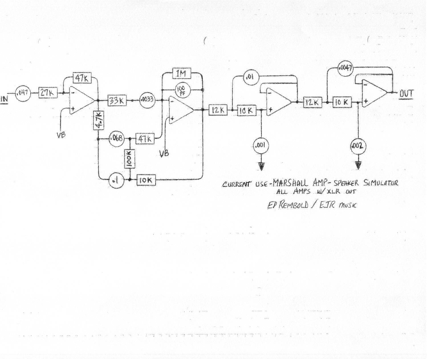
Thanks anyways Harald.
I’m also hoping that one of the folks jump in with a suggestion for one step further on this subject, what about also powering this unit with phantom power…. that I think will be wonderful, it will be like having a true soundboard ready cab sim.
I’m no expert on this, but I would think you’d need an added stage outputting the opposite phase to make this into a balanced output signal? I have yet to look into these things, so not much help from me I’m afraid.
I mean, exactly where to connect the pin 3 (negative) for a balanced output (line low impedance) while keeping the unbalanced output (high impedance) as well.
Guys, is there any way to know where to connect the XLR output on this one? I just want to add it to the circuit.
That’s good to hear, although it’s always irritating not knowing why something suddenly works differently.
Gudday Harald.
I’ve built Rev1 tonight and compared it to my original layout with the flying components. Maybe I’ve done something wrong with the added components but R1 sounds a lot better – the distortion isn’t nerfed. I’m much happier with it (worked first go too!)
Great, Willy 🙂
Thanks Harald, I’ve added those components in flying connections to the original layout and it works great.
Thanks for the heads up, Sam. I’ll change the input cap as suggested. Writing it on my todo-list now!
Took another look at the design of this today and realised that a significant amount of the high pass filtering in this design comes from the first stage. The mods to increase the input impedance of the revised version didn’t account for this. If the 27k input resistor is increase to e.g. 470k, then the input cap should be decreased a similar amount – in this case to 2n7. I doubt you could hear the difference if you used a 2n2 or 3n3.
And thank you for verifying, jack! 🙂
I just built the updated version of the marshall speaker simulator sounds awesome works perfect great sound its verified thanks for the vero.
Pierre, thanks for sharing. I have to admit I can’t tell, but I’ll make a guess and say the “a” clips are the simulator. Sounds pretty nice either way, though 🙂
https://soundcloud.com/user572545232/sets/marshall-speaker-simulator-vs
Hi Harald!
As I didn’t found any reviews on the net for this one, I built it and record some tracks for a friend.
I’m leaving here some samples comparison between this marshall speaker simulator and my G5 amp (http://www.projetg5.com/projets/g5)
Both samples are made with the wripletreck boost alone going into a black 65′ clone; tests 1 and 3 are played on a gretch and the second is played with a strat.
The thing is that I don’t know witch one is connected to the G5 or the simulator. Just guess! 😉
Sounds right, Willy.
SO… if I add C11 and R15 to my original build with a few flying connections I’ll be sorted? I’ve done the mods suggested in the thread – R2 now a pot, R1 is now 470k.
AFAICT, R15 just goes from the output to ground, and C11 goes from IC pin7 to output.
New layout now, but you’ve probably noticed that if you’re reading this 😉
Thanks for building, MikeT. Not sure yet what to do with this layout, but might have to make a revision with an output cap and a volume control.
I’ve built and tested mine Harald (would have worked first go if I hadn’t put the IC socket down a row too low), and had the same issue – it’s extremely loud. I’m wondering if it couldn’t use a 40db pad on the output or something.
It’s not really an issue for my intentions as it’s going to go in a box that has a volume pot at the end of the signal chain, but I’m probably going to put a couple of 20db pads in the circuit anyway. But yeah, thanks for the layout!
Some mod ideas to tame this beast. I will report back when I try them.
http://www.diystompboxes.com/smfforum/index.php?topic=104498.0
I built this last night, it worked and sounds great. But it is so loud… I mean, beyond usable output volume. If I ran into the circuit with my guitar only (single coil) out to the mixer, I had to hit the -20 db pad button, had the gain at zero and it still clipped. Only way I could use it was limit the signal going into (about 1/2 the normal pickup output).
I wonder if the “recommended XLR output” means it needs some kind of XLR buffer that can bring the signal down to normal levels.
You can call it verified, but watch out for the volume levels, it’s louder than a cranked SHO as is?
Awesome Harald! I’ll build this asap and let you know how it goes.