Update (10.07.2014): Minor changes to the schematic and vero layout to make it work properly with the tap-tempo clock project; tap input switch, series resistor and sync input.
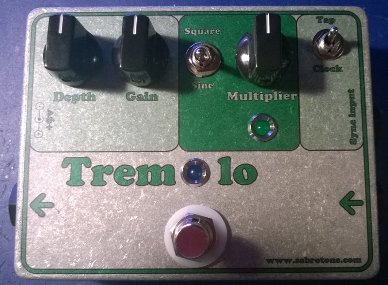
And here’s the logical follow-up to version 2 of the tap-tempo chip; version 2 of the tap-tempo Trembulator. By the way, since it’s no longer looking much like a trembulator I decided to name it just tremolo.
Again, this is with a 5-way selector switch to set the tempo multiplier, and a simple 2-way switch to select only between sine- and square wave. Additionally, there’s a DPDT for specifying whether the tap-tempo comes from a momentary switch on the effect or from an external source via a cable of some sort.
 Which leads me to another thing that has to be decided. If receiving a tempo signal from the outside, what would be a good cable/jack/plug choice for this? I don’t know yet.
Anyway, here’s the layout. Again, I’ve tested this on breadboard, so the circuit itself should be sound. But that’s not saying the vero layout is flawless. And you need to program the ATtiny85 with the tap-tempo v2 source code, of course.
This is the version I’m building, for sure! But I haven’t got all the necessary parts right now, so I will have to source it (which is probably going to take a month now considering the season). I’ll update as things progress, and if any of you are brave enough to give this a try before me I’d love to hear how that goes 🙂
Update (26.12.2013): Alternate vero layout. Having all those subdivision resistors on the main board seemed a bit redundant. I changed the multiplier input setting to a B10k pot, and if you want to use a rotary switch instead you can just run the “Multiplier 2” connection to the center lug and add the appropriate resistors directly to the switch. More flexible for everyone, and saves space too!
Update (15.01.2014): For some strange reason the 2.1 vero layout wasn’t clickable. Should work now, but do let me know if you come over others with the same problem.
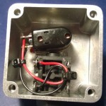
Update (24.01.2014): Built it and it works like a charm! No clock noise either 🙂

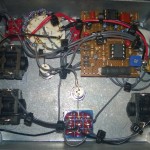
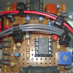
Not the best shot of the board, though, but I’m not about to remove those wires. You might also notice I’ve wired the tap-tempo/clock input jack slightly differently than the schematic. I’ll post a final schematic and layout, but it’s very minor, and the 2.1 will do fine.
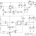
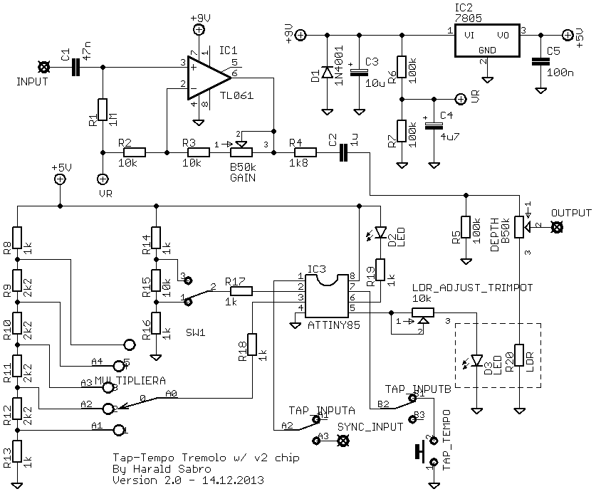
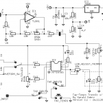
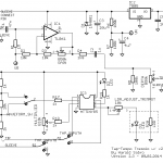
 Update (25.01.2014): And here’s the final (I would hope) schematic and layout, matching the build above.
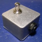
Update (13.02.2014): Found a small mistake on the schematic where the ground and signal wire on the clock output jack was reversed. And I got around to building a passive tap-tempo switch as a start.


Micah, I wish I could give you a straight answer, but to be honest it has been so long. I can’t remember what I changed between those two versions. What I can do, though, is dig out my build and purposely replace the chip with a v3 (I can’t remember which it has) and see if it still works.
Will see if I have time to try it this weekend.
Hi Harald
Will this work with the v3 chip?
Built it, but it seems to inject the waveform back into the input, which then leads serious oscillation.
Thanks for your work!
It’s a 5T rotary switch. Since the multiplier setting is defined based on the DC voltage on the pin; i.e. between 0V and +1V is first setting, between +1V and +2V is the second setting etc., you need a voltage divider connected between +5V and ground. An obvious candidate is a potmeter, but rather than a smooth, undefined transition between settings I wanted to be discrete steps with no ambiguity. Hence I wired up a rotary switch with several resistors connected in series and the ends connected to +5V and ground. Each step on the rotary connects to the junctions of two resistors allowing a specific DC voltage for each setting.
It’s actually much easier than it sounds. If you download the zip/documentation/source code I think there’s an example schematic for the rotary switch in there somewhere.
Hope this helps 🙂
Edit: shot not shit haha
Hello Harald, im wondering about the multiplier pot. What kind of pot is that? Your gut shit shows a lot of terminals with resistors soldered to it. Do you mind explaining?
Hi John,
It means both lugs #2 and #3 on the pot has to make electrical contact with the board at the indicated point. Now, this can be achieved in many different ways, but the easiest is probably to run a wire from the board to one of the lugs (doesn’t matter which one) and then add a small connection, like the remains of a resistor leg, between the two lugs.
Hi,
You connect lugs 2 and 3 of the Gain pot to the board after R4. I was wondering how that works. Should I take one lead out from the board, solder it to 2 separate wires, then solder each wire to its respective lug (parallel), OR should I solder a lead from the board directly to lug 2, then take another lead from lug 2 to lug 3 of the pot (series)? Sorry for the noob question, I’ve run into this with a EHX OD Glove, and noticed the similarity on this layout. Thought I’d ask.
P.S. thanks for this site, I’m addicted to DIY pedals now!
Interesting question, krz22.
I have no idea how a MIDI clock signal works, but odds are, given that I just implemented something that works for my use, they’re not going to match. I implemented it by interpreting each clock edge, be it rising or falling, as marking a full clock cycle. I.e. each clock cycle alternates between sitting at either +0v or +5v (works great for sync’ing several chips in real-time without clock cycle buffering delays).
Hi, first time posting here. I was wondering if I build this pedal with a 5 pin midi connector, can I use the midi clock to set the tempo on pin 1 directly? Or do I need a buffer circuit or a bridging circuit for the IC3 to accept the midi clock? Thanks, much appreciated.
You’re quite right! I thought you were referring to another issue. How about now?
Still cant click on the reduced vero layout, dont know why…try it
I noticed that clicking issue too, and I didn’t care for it, so I switched the look again (the turquoise one didn’t play well with the storefront stuff either). Hopefully this one is going to be better; my first impression is good.
And you should be able to access the store section when you read this.
Hey Harald, the updated vero layout is not clickable…just the schematic is.
On a side note, how’s that storefront going? 😛
Thanks guys 🙂 Lars, I thought about averaging to make it more precise etc, but it would also complicate things quite a bit. What happens when you get to the next song and need to change tempo? That could be problematic if the chip keeps averaging based on the previous tempo. You’d need some additional mechanism, like a separate switch, to indicate when to stop averaging. Or you could base it on time since last averaging input or something, but it’s still problematic.
Dear Harald,
first, let me applaud this site and your projects. This page is definitely among the top 5 of all diy pedal sites (and my bookmarks),
I really like tremolos a lot and built myself a nice little tap tremolo based on the electric druid’s versatile tapflo code.
The only feature I think really lacks finesse is the tap feature itself. I’d much prefer an averaging process. So the tempo is set by the first two taps but further tapping would improve the accuracy. I use a tempo analyser on my computer (tapping the space bar for displaying the tempo) an I observe that the accuracy after only two taps deviates quite a bit.
I think that would be a great improvement to this otherwise brilliant project.
Unfortunately I got myself a pic programmer (which seem a lot easier to burn than these AVRs. Is this so or am I looking at the wrong burners?) for that tapflo chip. But the ability to operate multiple tapable pedals PLUS that before mentioned tap-average would bring me to buy an AVR burner (and maybe finally getting into programming myself).
Best regards, Lars
Harald, I have no words for you man, what an ace!
I have never worked with the ATtiny before, but all of this that you are describing, just sounds like heaven.
I am really eager to see my pedals move from disoriented timing to a global tap tempo thing.
It’s an incredible idea to leave that DPDT to be able to switch from global tap tempo to the manual via pedal’s momentary switch. And here’s why, imagine you have global tap tempo and set the for a phase, a tremolo and a delay. I am guesing that would sound pretty boring, but then again if you set a different subdivision on every one of them, fantastic intertwined sounds are to be had.