Did a vero layout for the Oberheim VCF (Voltage Controlled Filter) / Maestro Filter Sample Hold effect today. Haven’t had the time to build it yet, but will try to source the parts I’m missing. I’ll get back with an update once I’ve built the thing.
Note that this layout has yet to be verified.
Update (17.10.2010): Finished building and testing the circuit. Decided to swap the S/H speed pot compared to the schematic, so that turning it clockwise increases speed. The direction switch seemed to be a bit strange in one of the two positions, but this might be a testing glitch or a mistake when populating the board. I guess the layout is verified at this point.
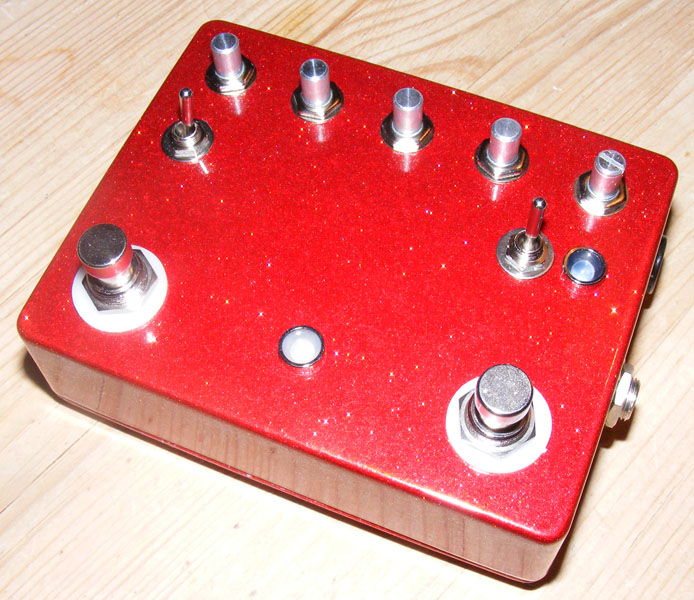
Update (03.11.2010): In the process of boxing this now. An optional indicator LED has been added to the layout visualizing the Sample and Hold speed setting.
Update (18.12.2010): I finally finished this effect. This has got to be the most troublesome build I’ve done so far. I’ve completely wired it up four times now, and this last time everything worked properly. In my first attempt the speed pot wires of the sample and hold effect injected a really annoying control signal ticking even to the bypassed signal. My second attempt saw me reorient the board inside the enclosure and use shielded wire for the output signal. This solved the ticking noise, but the filter/auto-wah effect just refused to work at all. My third attempt gt me nowhere closer to solving the auto-wah, but on the fourth attempt, tonight, I finally found the problem; the attack pot had gone bad. Replaced it, wired it all up, waited for the moon and all the stars to align, carefully put the back of the enclosure on… and it works!
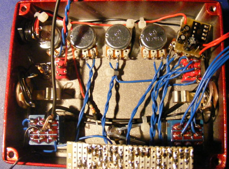
The gut shot is an intermediate state, before I got all the wires hooked up, but shows the inside layout. Notice I placed a small charge pump circuit on top of the right-most pot using a bit of double-sided tape. The charge pump enables me to also get -9v DC internally so I can run the effect on a regular +9v DC power supply and still be able to feed the circuit the required +9v/-9v. I also need to get some knobs attached to those potentiometer shafts.
I’ve got the reverse sweep switch on the left and a SH speed visual indicator switch on the right-hand side. I didn’t find the reverse sweep all that useful myself, but it doesn’t hurt to have the switch present. I also decided to make the filter switch “stompable” so I can go between auto-wah and sequencer mode on the fly. I wired this up with a dual LED similar to how I did the Bad Cat Hot Cat emulator (see that post for a wiring schematic).
The speed indicator LED is also worth mentioning. My friend Jon thought it would be great if we could have a visual indicator of the speed setting on the sample and hold effect. This was readily available by connecting the positive side of a LED to pin 7 of IC4, but by doing so we also altered the tuning of the sequencer. Therefore we added a toggle switch to lift the LED from pin7 giving us the option of turning on the visual indicator LED while adjusting the speed and then turn it off again before playing.
Based on my own experiences with this thing I’m hesitant to recommend others try to build this, at least if you’re just beginning, but of course your mileage may vary…
Update (30.06.2011): Here’s a new vero layout for the Oberheim Voltage Controlled Filter / Maestro Filter Sample & Hold. This one is based on the tonepad schematic and uses an LM13600 instead of a pair of CA3080. I was also able to squeeze in both the input buffer I left out of the first layout and an onboard charge pump.
Update (20.10.2011): Fixed dead layout links.
Update (12.03.2012): At last! I got around to building the version 2 vero tonight and it works quite well actually. I tried a few different transistors for Q1, and the 2N3904 didn’t do anything at all, but I reasonably good results with both 2N2222A and 2N3703. I’m going to do a more thorough search for Q1 when I box this, and the layout may still have a few of the pots wired in reverse, so I won’t mark it as verified just yet.


Just to add – I found the filter far more responsive using 1n914’s in place of the 400X’s
Possibly, but I can’t tell you for sure. I know very little about synths. If you do try, make sure your components are rated for the higher voltage etc. And do know this is quite a whimsical circuit that could prove a frustrating build, at least that’s my experience.
Does it work with +/-12v? on a eurorack modular synth?
The optional LED connected to pin 7 was intended as a visual aid for the “speed” setting of the sample & hold part of the circuit and not really meant to replace the standard indicator LED you’d use to show whether the effect is on or off, but I guess it can be used for that.
The LED cathode (-) connects to ground via a limiting resistor of your choice, maybe 4k7?
Correction to previous post:
By switch I mean 3PDT.
http://www.tonepad.com/getFile.asp?id=96
Thank you,
John
Hey,
Quick question.
I have my LEDs connected to the 7th pin of the ICs and the – connected to top center on the switch. They do not pulse LFO or do the up/down swell or decay. Is this the source of the problem? Where should I connect the negative end?
Thank you,
John
Hello Harald,
I wanted to let you know that I’ve built version 2 somewhat successfully. There’s clearly a noticable ticking, but it seems to be a very common problem with this circuit.
According to my intuition, the attack and resonance pots should be reversed.
I used a standard 3904 as noise transistor, and for some reason the effect only worked with a BF244A as Q6. (maybe because I only had BF245C’s instead of 245A’s?).
Thanks for all these layouts!
Hello Harald, sorry about the late response.
Yes, I tried the original and all I got was a very loud noise when the effect was engaged.
As for Q1, take a look at the first comment on this youtube video:
http://www.youtube.com/watch?v=5x_2F6iOYkg
“I used j201’s instead of the FET’s listed by tonepad as, no amount of stuffing around with them would get them to work. I also used a 2n5088 for Q1. This combination was the only way i could get mine to work.”
Well I tried this combination and it also didn’t work. So I kept the BF245A in Q2, Q5 and Q6, and put a J201 in Q1, just to see what happened. Surprisingly, it worked!
I still haven’t gotten around to doing this one.
i’m also very interested in building this.
has anyone verified the v2 layout?
/christian
I just had another look at the vero, schematic and pinout of the LM13600 and you’re right, the pins are different. But, and I think you mentioned it, since this is a dual OTA it should work as advertised, it’s just that I’ve interchanged the two OTAs compared to the schematic. Did you try the original layout without luck and had to mirror all the relevant pins to get it to work?
As for the transistor I did put a note on there saying to try different NPNs. You had luck with a J201?
Oops, that’s a lot of pins I got wrong! I’ll have another look at the layout as soon as I can. Thanks for letting me know, John.
Oh, forgot to link said thread:
http://www.diystompboxes.com/smfforum/index.php?topic=69638.0
Hello Harald!
Great news, I’ve just finished your layout, found some problems, but got it working in the end!
When I finished assembling last week, I plugged the guitar in and it was noise everywhere, no matter what switches I pressed or knobs I turned. I was having a bad day, my dog wouldn’t stop barking for some reason, and I couldn’t figure out what was wrong, so I gave up, put the vero in the drawer and went to sleep.
Today I finally got the strenght to pick it up again… So after a quick look at the Tonepad layout, I found that the pins on the IC1, on that layout, were different from yours. So my guess was you interchanged the connections on some of those pins. In fact, you got these pins right: 1,2,6,11,15,16. The rest of the pins however, are all interchanged.
Also, 2N3904 didn’t seem to do anything in the S&H mode. I put a J201 instead and it worked just fine.
I have a small ticking noise when I engage S&H mode. I’ve read ticking is a common problem associated to this circuit, and there have been some people trying to get around it… I’m following this thread and will try any of their solutions any time soon. In the meantime I will also be experimenting with different transistors.
Apart from the IC1 pin positions and the transistor, your layout is correct and functional. I’ll write since I have anything new!
Thank you once again.
Cheers,
John
Hi, John. No news from me yet. I’ve got everything here ready for building, but no time! I promise to update as soon as I get it done. I do remember having lots of trouble getting v1 to work properly, though, so I’m a little reluctant to jump to it.
And thanks for the kind words 🙂
Hello Harald!
Any updates on the status of the V2 layout? I’ve already ordered the materials needed to build it and I will start next week. If you or anyone else has updates about this circuit, I’ll be glad to hear them before I start this long adventure
Thanks Harald. By the way, awesome site you have here. Instant bookmark!
Cheers,
John
Just saw the new layout! I’ll definitely try it once I source a lm13600. I think it was the cheap ca3080’s i got on ebay that were the issue with that build. I got like 5 of them for $4. At least 2 of them worked…
That’s great, and quite a challenge fitting that thing into a 125B! I didn’t run into the CA3080 issues you described, but still I’m actually working on an updated layout using the LM13600 that I’m also trying to cram a charge pump and the input buffer into it.
Just wanted to write back and say I successfully built this, definitely quite a build! The issue I had getting it going was finding the right ca3080’s, luckily I had a few on hand. I fit it in a 125b size enclosure as well, just didn’t put a bypass switch on it. My board has looper true bypass switches on the bottom and real estate is to a minimum so this worked great. Thanks again Harald for the awesome layout!
Gotcha,I figured as much when I saw a similar setup with the caps on the charge pump vero.
Thanks Harald!
C9 is correct because the effect actually requires a bi-polar power supply to run correctly. i.e. +9v/-9v. You can achieve this by using a charge pump and a regular +9v power supply. There’s a layout for a simple -9v charge pump in the “other” section at the bottom of the vero layout list.
Is c9 reversed in the vero layout? I notice that the positive side of the electrolytic is going to ground.
Harald,
I’m not really understanding the switches numbering on the vero layout. Any chance of some more info or a graphic on the switches wiring?
thanks!
Gray
The offboard stuff was indeed the hardest part. Good luck with your build, and let us know how it ends up 🙂
well, I’m going to give this one a try based on your vero layout, wish me luck. Sounds like most of the difficulties were with the offboard stuff, right? The stompable filter switch is a good idea, I’ll have a run at that as well.