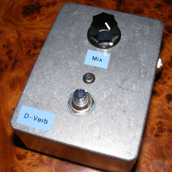
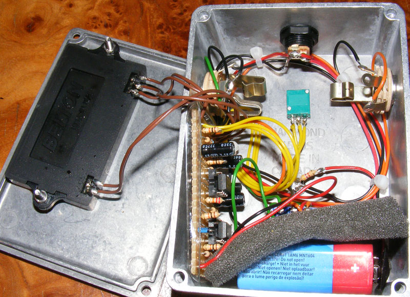
Recapping a few of the effects I’ve made recently here’s my take on a Digital Reverb circuit based on the Belton reverb unit. The layout worked great, but fitting the reverb unit in the enclosure I had at hand (I believe it’s a Hammond 1590S) proved a challenge. I ended up attaching it to the bottom of the pedal.


I expected that, but good to have it confirmed 🙂 Thanks for sharing, giorgione84.
i have build it with btdr-2 and i can confirm that it really works!! you have only to check the right pins to wire to the circuit. Thanks again
It will probably work fine with the newer (and smaller) BTDR-2, but there are two pins that have swapped places between the two versions so you have to take that into account. The datasheet for both bricks should be available at accutronics’ site.
Hi harald. Just a question. Do you think that this circuit works with btdr-2? Thanks
This is a great sounding verb! Thanks for the layout (and all the others, too).
Happy you solved it, Pierre 🙂
Hi!
While having a problem with a loss of volume switching on this effect, I finaly found out the solution replacing r7 with a jumper.
Nice effect, great sound, congratulations!
Hi!
I am experiencing some volume drop switching in this effect. Is there a solution?
Best regards
Pierre
Hey Vincenzo
My layout is based on the GGG schematic just like Harald’s, so there should be no difference. The little pieces of wire ARE connections. Please note that R9 and R10 share a hole, and that you didn’t forget the cuts below D1 and R12. Also R12 is connected to pin4 of IC2. Sorry for the layout being kind of messy, compared to Harald’s anyways.
Good luck if you decide to give it another go! And even though I think everything should be clear now, if you have any more questions about my layout, contact me personally here http://oi45.tinypic.com/2dij29s.jpg – no need to bother Harald with this 😉
Those voltages do look a bit high. Are you using a 12v adapter and not a 9v one? The reverb brick requires +5v so that might be why it’s not working, though the 78L05 regulator should provide this. Maybe 13v is too high for the regulator to work wit hand that’s why it’s giving 7v?
As for the connectors between pins 1-2 and 6-7, yes they need to be connected. You’ll find them on my layout as well in the form of jumpers (one of them is underneath the IC socket.
Hello Harald,
I have checked the voltage on the ICs (pin 8) and the transistor. I got pretty strange results:
12.58v on the ICs.
12.58v on the transistor’s input.
7.02v on the transistor’s output.
And the BTDR-2 gets around 7v too…
I found that pretty strange, so I decided to check my Boss PSA’s voltage with the multimeter and it gave me 13.24v… Didn’t try with my Voodoo Labs Pedal Power 2 yet.
I don’t really get it…
Also, on Bart’s layout, there are links between some ICs’ pins (http://i41.tinypic.com/ibwboz.png pin 1 to pin 2 and pin 7 to pin 6 on IC1 and also IC2’s pin 4 to R12). I’ve always done the build with these links but maybe they do not symbolize a connection, do they? Since I have triple checked every component,
One last thing: one hour ago, I plugged it to my guitar and amp tu test it, but I had forgot to put the ICs on their socket. Of course I had absolutely no signal BUT when I switched the pedal on, there was this usual click we get when there is no pulldown resistor and it was reverbered. It sounded exactly the same as my friend’s Malekko Spring Chicken when turned on. So at least I can tell myself I have done something well… A little consolation price haha…
Thanks again for this wonderful website.
Vincenzo
Now I am actually getting sound from the build, but I also get loads of noise, the knob doesn’t change anything to the sound (100% wet, I think because of the latency when I play) and everything sounds totally distorted… But I can perceive the quality of the reverb trough all this mess and it is a fairly good reason to keep on trying. I’ll get back to this tomorrow.
Now I found my mistake: I had reversed 3 and 4 on the BTDR-2. Tried out again, still doesn’t work… But the sound has changed. Now I hear a very quiet (almost impossible to hear because of my amp’s hum) an a little distorted with a reverb! It is SOOOO frustrating: it seems to sound amazing but I am unable to get it to work better than this… I am going to measure the voltage between the belton’s V+ and the Ground… Let’s see what happens.
Hi Harald,
Thanks for your quick response. I have checked the pinout of both 7805 and 78L05, and, on both, pins are ordered the same, so my mistake has probably been done in another part of the process… I haven’t yet got to mesure the voltage on the belton brick, but I will do it in a few minutes.
Again, thanks a lot for taking the time to give me an answer.
Have you checked the pinout on the regulator (Q1)? Measure the voltage on the BTDR-2 using a DMM and make sure it’s getting the requisite +5v.
Hello Harald,
I just finished my take on this reverb (I used Bart’s layout and BTDR-2 because I didn’t want to have issues when putting everything in) and instead of behaving like a reverb, it sounds like a super gated fuzz… It sounds cool actually but I don’t think I need this kind of sound right now! Haha!
I have absolutely no idea of what possibly went wrong except that I used a 78L05 instead of a 7805 for Q1. Have you already experienced this kind of behavior from one of your builds?
Looks great, miro!
http://mirosol.kapsi.fi/varasto/boxes/dverb.JPG
+m
Boxed this today and it is really that good. Since that BAT46 is just for power and reasonably hard to source, i used 1N4001 instead. Don’t think that affects the sound at all.
It’s perfect digital reVerb. Recommended build.
Thanks Sabro!
Hi Wesmo. This is a digital reverb unit/black box ready-made for diy. I’m not sure if Belton is the name of the unit or the company making it. You can buy it at several of the established diy guitar parts sites (look at the parts sourcing links on the right-hand side), I’ve bought mine from smallbear.
Do note that the layout you’re looking at now is for the older version of the Belton. They recently came out with an updated version that’s about half the size of the original one, but it has a different pinout. I recently posted a layout for the new version too, but it has yet to be verified.
Sorry if i’m not that smart, but what is Belton 1 through 7?
And the Belton tank?
Not really, but I’ll consider it.
Have thought abouth vero layout that would use analog reverb tank?
I would assume not as this one relies on a digital reverb unit.
Hmm.. Could this schem/layout be transformed for use with spring reverb tank?
Just built this one too! But I have to admit that I used Bart’s smaller layout because I used the Accutronics unit! 😀 But it’s really really good sounding reverb, not too “invasive” and very warm. Btw I suggest everyone to buy the Accutronics unit as it’s really small and light; maybe, Sabro, could you just add the wiring for it in your layout, as the pins are different? Thanks! 😀
Alright! That’s good to know. I might have to revisit this reverb 🙂
I built this a while ago with Accutronics BTDR-2. It does work, and it works great! The BTDR-2 is capable of stereo output but you can just use one output if you don’t need it.
Also I don’t mean to brag, but my layout is also slightly more compact 😛
http://i41.tinypic.com/ibwboz.png
I would assume not until proven otherwise, but you never know. Have a look at the datasheet for the reverb module in question. Afraid I don’t know enough about reverb’s to give you a good answer, sorry.
Would this circuit work with an Accutronics Digi-Log BTDR-2H Long reverb brick? I realize I would have to ensure I get the correct pinouts, but otherwise the circuit should be the same, correct?
Thanks!
This is a great little project. Built it with a medium dwell brick and it sounded really ‘surfy’.
Those are the places you need to cut the vero strips. Look at the “step by step” section for a quick tutorial.
Hey! I am aware that everyone will look at me like 0.o but I want to ask: what are the red dots in red squares standing for?
Thanks:)
Very happy to hear this, David! Now, I still think you should invest in a DMM for your next build 😉
After hours of trying to resolder the tracks so there’s no way they might be touching each other I figured out my problem- I put the voltage regulator one hole too low 🙂
Don’t know how I missed it…
Anyway it works now and sounds great!
Thanks for the help Harald!
Thanks Harald, i’m gonna borrow a multimeter from a friend next week, until then i’d still like to try and solve this issue.
I grounded the output jack, didn’t make a difference.
Is my picture not clear? How I wired the off board is In from board to input ring, Out from board to output ring, 9v from board to DC jack middle lug, ground from board, output jack sleeve and DC jack right lug to input jack sleeve.
David, a short could very well result in the problem you describe depending on what parts of the circuit it bridges, and is also a common problem even for experienced builders. I strongly recommend getting a basic, inexpensive DMM as these are virtually indispensable when trying to solve problems like this.
Hard to tell if your off-board wiring is correct from the pictures you posted. Both input and output jack sleeves need to be grounded, but you need only connect a wire to one of the sleeves as long as you use a metal enclosure (the other sleeve will be connected to ground via the enclosure itself).
Hi, Ben. No. Without having any actual experience with XLRs, balanced output and line level I do believe you’d need some extra circuitry to make this work.
I don’t have a multimeter so it’s a bit of a problem.
If I had a short wouldn’t I get no signal at all?
I did go over the tracks with a magnifying glass and made sure none are shorting each other and that the cuts are correct.
I looked up the specs sheet of the L7805 online and oriented it according to the pinout there.
Is my offboard wiring correct? I didn’t connect a ground wire to the output jack’s sleeve, does it matter?
Thanks Harald
Hi Harald,
a quick question about the D-verb. Would it be possible to add a XLR jack to use the effect with a microphone? Do you think it would work ? or is it just an effect for guitar?
thanks for your time.
Ben
It’s a bit hard to tell looking at those picture, but I’d start by looking for shorts.
– Use a multimeter with continuity test and systematically make sure no two adjacent tracks are connected, and if they are there should be a jumper involved on the component side. Also make sure all your cuts actually break the vero track completely.
– If all checks out go to the component side and make sure no component legs touch either.
– Third, again using the continuity test, make sure all wires connect properly to whatever lug/hardware they’re supposed to.
– If everything still looks OK double and triple check that you’ve placed all components correctly, that the polarized ones are oriented the right way, that you haven’t forgotten a component, jumper or cut, and that the pinout of your particular voltage regulator matches the layout (apparently this can vary with manufacturer/packaging).
– Double check your wiring.
– When the effect is powered on you can use the DC voltage setting on your multimeter to make sure pin 8 on each IC measures approx. +9v. The input on the 78L05 should measure approx. +9v as well, and the output should measure +5v.
Thanks Harald.
I finished the build today, I built it into a 125 sized enclosure with no footswitch and battery. The reverb isn’t working, I get a signal but it’s like a bypassed signal- no effect no matter where the knob is.
I’ve uploaded pictures here:
http://www.freestompboxes.org/viewtopic.php?f=28&t=6179&p=149908#p149908
I’d appreciate if you could help me debug this issue.
Thanks!
Hi, David. Pins #2 and #6 are left unconnected, and you’ll find a picture with pot numbering under the “schematics & drawings” page (with the shaft pointing up and the lugs pointing towards you they’re numbered 1-3 from left to right). Good luck!
Thanks for the great layout!
Where do I solder the belton 2 and 6 terminals to?
How do you number the pot’s lugs?
Thanks
After trying a few tweaks here and there, I found it to be best left stock. A very nice sounding reverb, not too over the top. With some extra careful planning I managed to just barely squeeze it in a 1590B.
Thanks for making this layout available 😀
Here’s a grainy photo of it all boxed up: http://i56.tinypic.com/2vvm5mr.jpg
It’s on the left next to two other builds of your layouts, the Way Huge Aqua Puss (middle) and although hardly visible, the Okko Diablo (right).
I haven’t really got any suggestions for you other than to breadboard it and give it a try. I built it “stock” and was happy with that. Good luck! 🙂
Hey Harald,
I plan on building this in the next day or two (once my soldering station finally shows up in the mail). I’m curious about a few things though. Would you have any suggestions for adding a tone control to the reverb? Looking at the schematic I’d assume it’d be placed before lug 3 of the Mix pot. Maybe a BMP tone control would do? But the BMP tone control is lossy, so a gain stage would probably have to be tacked on if that were to be done.
I’ll probably end up building it stock, because I just want a simple sort of reverb, but I could always tweak the capacitor values after the fact to something that suits what I’m looking for.
Just curious of your thoughts towards this.
Cheers!
I’m not sure about the BAT46, but it looks to me like a regular surge protector so I suppose you can swap it with a common 1N4001 or similar. By the way, I sourced mine at http://www.elfa.se.
Q1 is a 5 volt regulator in a TO-92 package. Smallbear carries them, as do mouser (LM78L05).
Hi there, I was wondering if you could substitute another diode for the BAT 46 which are pretty hard to come by in Japan. Also, is Q1 a tranny? That number looks like nothing I’ve ever seen before, more like a voltage regulator. Are there any substitutes for Q1? Cheers, thanks for the layout!