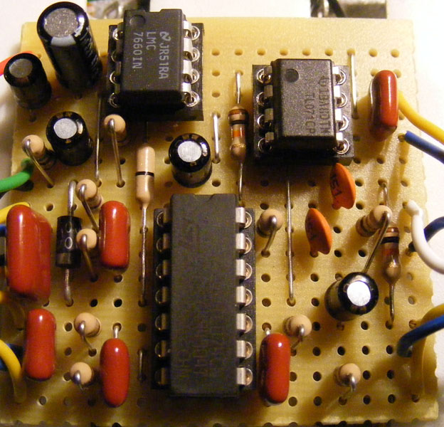
Here’s my first attempt at a parametric equalizer. I combined parts of the graphic equalizer I did previously with information on how to make gyrators from R.G.Keen at Geofex. There’s a schematic and a vero layout, and I haven’t verified either yet. Updates to come soon.
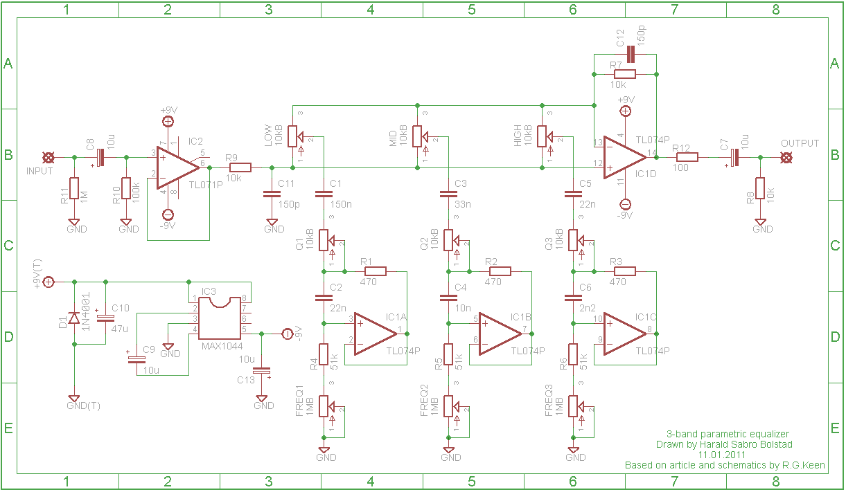
Update (13.01.2011): Correctly labeled C1 as 150nF and not 150pF.
Update (24.02.2011): Built this circuit yesterday and I can hereby verify it as working.
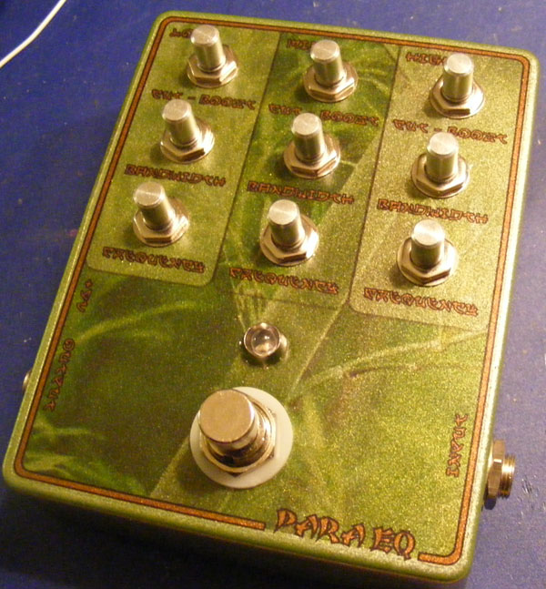
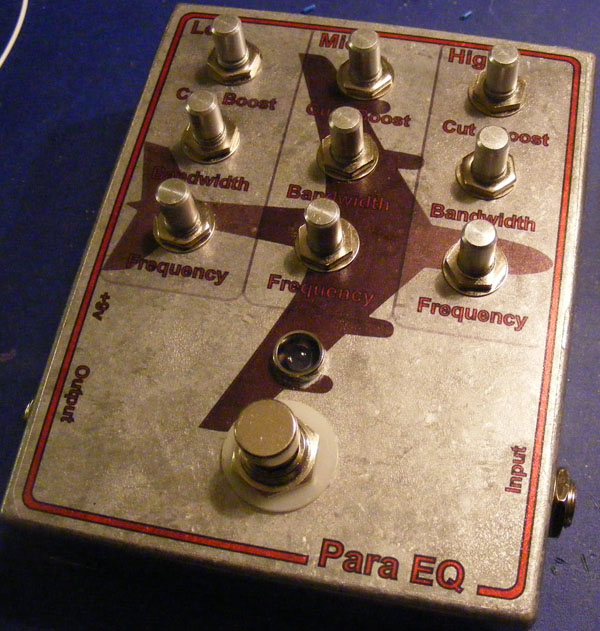
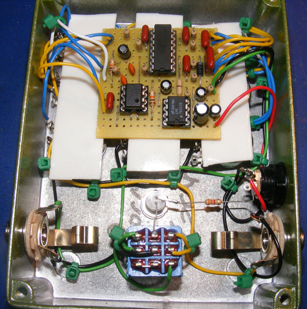
Update (29.03.2011): Boxed this effect last night with a friend. This is my second take at using a transparent film for artwork and labeling, and it came out a lot nicer now. Only thing missing is a few (many!) knobs.
Update (20.10.2011): Fixed dead picture links.


PCB layout pls
Hi Harold,
I’m trying to build your Sabrina 3band para eq, but I’m having a bit of trouble with the wiring to some of the pots. Particularly with the “boost” and “cut”, can you show a more clear picture of the wiring for these from the board to the pot? In the pictures you show, all the pots are covered up and the layout picture doesn’t number these, and I’m having trouble making sense of the schematic, this is very new to me so sorry if this is a dumb question.
Thanks man
Hi Harald !
I just built this EQ and it sounds amazing for the low parts count. Thanks for your work !
I just would like the bass freq pot to go lower, and the high freq pot to go higher. Do you have any idea where I should change values ?
I have no idea what the current consumption is. Never tried it.
Hi,
I’m just wondering if i could put this onboard of a guitar or bass, but I have a question:
do you know it’s power drain or 9v battery life inside it?
Awesome site, thank you for all your hard work. Can this be used as outboard gear, for mixing through interface? If so does anything need to be altered?
Thank you
Many mistakes on the vero. IC3 should be IC3, IC2 should be IC1, IC3 should be IC2, R7 should be R9, R8 should be R7, C6 should be C12…
The labeling is all fucked but Is should work… but the labeling on the schematic and the one on the vero really don’t fit together!
Hey,
thank you for the layout, it works like a charm!! I just ordered a few NE5532s they might be a bit quieter as the circuit is a bit noisy, especially if you boost the high frequencies… But anyway, great Equalizer nonetheless!
Best regards,
Lennart from Germany
I’m not in a position where I can comfortable argue either for or against when it comes to electronics theory, but I can assure you it does actually work in practice.
Hi,
thanks very much for this layout.
There’s one thing i don’t understand though : how can the Q low 1-2, Q mid 1-2 and Q high 1-2 be positioned on the same line ? It would mean that moving one would affect the other ?
Thanks again
Nico
I’m not sure how dependent the “pots” are in the calculator, but they seemed to work fine in the circuit as far as I can remember (been a few years though).
Hallo,
the controls for Q and Freq are independant? i mean: rotating the Q pot will only affect the Q value or will it also affect the frequency setting (and vice versa)?
i tried to tweak values with the Gyrators calculator and noticed that even changing the value of only one resistor (i.e. R1) will affect both Q anf freq
thanks
Dom
1) You can use any configuration of pots you want as long as they have the correct value. It would be hard to find one with a combined 1M/10k though. Maybe if you found one with 1M/1M and you put a 10k in parallel with one of them?
2) It has an internal power IC that takes the +9V you give it and convert it to +/-9V = 18V on the inside, so there’s no need.
3) A gain pot can be added, but it’s going to be difficult with the current layout. You’d have to add a potmeter and probably also anothe resistor, while rearranging several components.
Hi Dennis,
I did that one several years ago, and I can no longer remember why I did it the way I did. It would probably look a bit different if I did it today.
Try the 100n caps. They may help.
khemahl,
Wish I had written it down. I can’t remember what they are.
hi guys .. My ma,e is giuseppe caporusso and i just love this preamp , but i’m not very expert with electronics .. and i have 3 questions :
1)is there a way for using stacked pots for boost/cut and freq ?,
2) could it be used 18 v power for more headroom ?,
3) could be added a gain trimpot ?.
Thankyou in advice
Giuseppe Caporusso Bass,Drums and Organ player .
Hi Harald,
Nice design but why arent there any decoupling caps for the opamps? i think adding these to the power lines of the opamps will reduce noise. I will be building this the next few days with the decoupliong caps of 100N in the minus and plus voltages lines and i will report back.
br, Dennis
what are the frequency ranges for each band?
dave, you might be right. I haven’t looked at any of this for quite a while. Though the build I did seem to work quite well with the stated cap values.
I’ll keep this in mind next time I revisit the EQ effects.
The equation being f= 1/(2*pi*(SQRT R1*R2*C1*C2))
Where r1 is the 470ohm and R2 is either end of the potentiometers, meaning 51k and 1.05M including the 51k resistor. If you leave C1 and C2 as nF they give quite outrageous values but when adjusted to pF they give realistic frequency values.
Has any one built this circuit with the given values if so did it work.
Hi there I was messing around with equations for the frequencies and found some surprising things with your frequencies. Are you sure your capacitors aren’t supposed to be in Pico farhads. When I changed them to Pico I got frequency ranges like 3-124 hz for the low range and 394-1789hz for the mid and finally 1029-4627 hz for the high range.
Sorry for not getting back to you earlier, dale.
First the pop; make sure you’ve got C14 oriented the correct way (rev.1 layout should be correct). Also, try connecting a 1M resistor from circuit input to ground.
As for the 1044 I couldn’t say with any certainty, but I’ve heard several of these voltage ICs having high frequency noise, and supposedly the “S” prefix fixes this (do check the datasheet for the IC in question though). You might also be able to use a 7660 or an LM1054 chip.
Hi Harald.
Is the 1044 chip a special suffix. Other pedals say ‘only’ the 1044scpa on some builds.
will any 1004 chip work or is there a good sub.
Trying another eq…..fun fun fun
dale
Hi Michael,
Boost/Cut pots set to the middle don´t change the sound significantly, but it did color the sound slightly (like most graphic eq when engaged). It is quiet in that position, and you can tell that moving up or down will add noise (again, just like any graphic eq…) – it is subtle and greatly benefits from tidy wiring.
Q value – This pot is really interactive with Freq. When both are fully ccw or cw, Q value is low, so it will work on a restricted bandwidth. The more the pots are opposed in direction, higher the Q value, so it will work on a broader bandwidth.
The maximum gain is relative… If the Q is low, it will boost/cut the given frequency with more power. If the Q is high, it will boost/cut with less intensity, but it will affect more frequencies. The perceived volume will be then, pretty much the same.
Final note is that it won´t give you a really strong boost, but it can taylor your sound in really good way.
Thanks André and Harald!!
How does the Q pot affect the Q value? I assume using the calculator on http://www.muzique.com/lab/gyrator.htm is when the Q pots are set to zero? How do i work out what my Q range is?
Also, roughly, how many db boost/cut does the gain pots provide? Am I right in saying setting the pot to the middle virtually ignores that band? I want to try and boost (0 to 8db’ish)
Cheers.
As you say it should be pretty straight forward to figure out what sections to remove, but you may have to do a little bit of tracing. Both the schematic and layout is available, however, unfortunately for you I drew these before I saw the value in having the component labels match (I do stupid things all the time).
Alternately, build all three bands, and just wire the pots for the one band you want to use. Leaving the other two there shouldn’t hurt.
Oops, you mentioned the website already… Thinking of the low frequencies, r1 is 51k, r2 is 470 ohms, c1 is 150nf and c2 is 33nf… You figure the rest.
The pots are there to give variations over the response, you can choose the values using the calculator, or just add some trimmers to help you tune things, which i highly recomend! Good luck
Michael, check this site http://www.muzique.com/lab/gyrator.htm , it has just what you need. I dont see why it wouldnt work with a level line input, should be just fine. You should probably work with trimmers for q and freq, though. It is good to have some variation…
Hi, great site!!
I would like to use this circuit as a filter for one of my projects with a few alterations, but am a bit stuck.
Will this work on line level inputs?
I would like to change (remove sections) so that it becomes a single-band parametric equaliser, which seems simple enough as the circuit seems to be modular.
I would also like to hard set the “frequency” and “Q” so that only the boost/cut is adjustable. I had a look at http://www.muzique.com/lab/gyrator.htm but am not sure which components link to what in the circuit diagram.
Any help is much appreciated.
PS: vero board is awesome.
I’m still not comfortable with the theory side of things, but I’m thinking the input impedance is going to be IC || 1M || 100k, so less than 100k. But going a bit further I’m not so sure that 1M is needed at all since the 100k also subs as a bleed resistor. How about removing the 1M and just replace the 100k with 4M7? This would give you 4M7 || IC ~= 4M7 input impedance? Correct me if I’m wrong, please 🙂
Hi Harald! Thanks for the great page, so many great stuff! Wish i have met you when i lived in Norway. Regarding this great project, i want to adapt it for using it with a harp mic. Crystal mics requires quite a high input impedance in order to keep the low end. The first 1 meg resistor is a pulldown, so i believe that the impedance is defined by the 100k resistor next to the 10uf cap. If i changed this to 4m7, it would probably be more adequate in my case. Do you think there would be side effects to the whole effect after it? Thanks a lot!
Jimmie,
“boost” on the board connects to lug #3 on all the “boost/cut” pots, same as “cut” on the board connects to lug #1 on the same pots.
As for crosstalk etc. treat it as any high-gain effect when wiring it (FAQ for tips).
Im currently wiring this one up and im wondering about J17 on the layout that says only “Boost”, where is that one going?
Also, you mentioned to be careful with wiring this to avaid crosstalk, any specific things to think of, wiring certain wired togheter etc?
I remember using this nice calculator fooling around with different values until I had something I liked: http://www.muzique.com/lab/gyrator.htm
May or may not have gone for different values today, but I do like the final result.
I guess theres no demo of this one? 🙂
Any idea what area the mid section sweeps?
I would need something that i can boost around the 1khz area without boosting a range to wide.
Hi Harald,
I was trying to make the equalizer more bass-friendly but I don’t know which caps to change. I’ve found these infos on bass frequencies:
http://www.diyaudio.com/forums/instruments-amps/32205-bass-guitar-frequency-range.html
Could you suggest me what to do from them?
Thanks
Hi Harald,
I don’t know if this could be useful but I’ve found some informations about bass frequencies here:
http://www.diyaudio.com/forums/instruments-amps/32205-bass-guitar-frequency-range.html
Hi Alex. Thanks a lot for the great offer, but I’m going to regretfully have to decline. I already have too much going on as it is and I likely wouldn’t be able to do it justice. But it would be a great idea having a collective space where everyone could add layouts. Hmm. Again, where’s the time…
Hi Harald,
It was for a friend and I don’t know much about bass either.
I really love your website and I can’t thank you enough for it.
I’ve been drawing some circuits using the same DIY Layouts program you use.
Some are those that some people have requested you and I’ve already verified them (Marshall ShredMaster, Death By Audio Robot,…).
If you want I can send you the original layouts files and, once you’ve double checked them and possibly corrected them, you can put your name and add them to the website.
I wouldn’t want my name to appear on them.
It would be just a way of thanking you for your great work.
Please, let me know if you could be interested.
Thanks Again
Alex
You will probably need to swap out a few caps to shift the frequencies down. I don’t know that much about bass guitars. What frequency spectrum does a bass cover and what’s the center frequency?
Hi Harald,
Any modification instructions for bass?
Thanks
Chris. I can’t remember what they are at the top of my head (and I didn’t write it down either), but try this calculator and you can come up with your own frequencies even: http://www.muzique.com/lab/gyrator.htm
Hi,
This site is amazing!
I’m planing to build this for tone-shaping.
Only one question: Could you please me about the Low/Mid/Hi Frequency Range?
You should probably adjust the frequencies for bass, it’s set up for guitar as it is now. Let me think about it for a bit and I may add some modification instructions to the post.
hi Harald,
can i use this eq for bass guitar..?? how about the frequency range, is that dedicated for bass guitar too..??
Hi Harald,
You are right the components are labeled different. That was confusing me a bit.
Thanks
Hi, Stefan. Thanks for the input, but you have to excuse me. I’m not entirely sure what you mean. Do you mean the polarities or the fact that I mislabeled almost all of the components compared to the schematic?
Hi,
I noticed that C12 and C13 are interchanged in the vero layout.
Best regards and thank you for this great site.