Here’s a vero layout for the OKKO Dominator as requested, based on the recently unveiled schematic over at freestompboxes.org. I haven’t verified it, but I went over it a few times and corrected some minor mistakes. It looks OK now.
Update (14.09.2011): Updated the vero layout based on Saruman’s revised schematic.
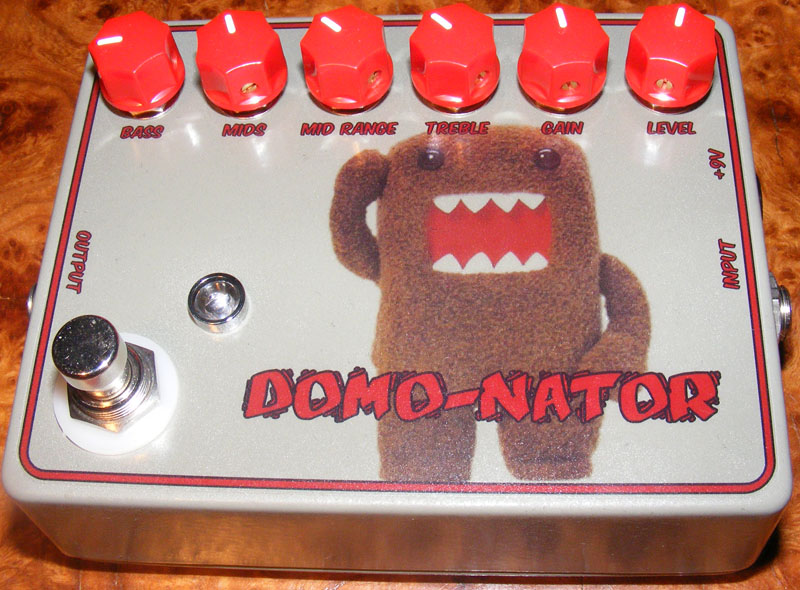
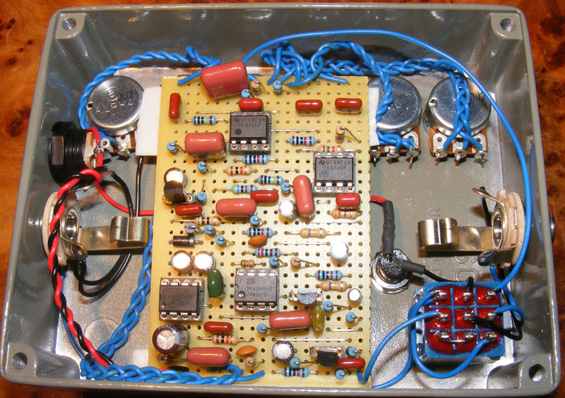
Update (25.06.2011): Here’s how my take on the Dominator ended up looking. Fairly cool, and it sounds great! An aggressive beast, this one.
Update (20.10.2011): Fixed dead picture links.


Thank you. I think I’ll buy metal films at the same time I’ll buy “amps”.
– Pet
It’s a case of using what I had in my drawers. I can’t say that I hear any difference between the carbon and metal film ones (though I haven’t really invested any time in A/B-ing either), but I do like the tighter tolerance on the metal film.
Hello. Nice “guide” You’ve made… I’m just curious to know – before I start to make my Dominator – have You picked up the resistors (in the pic. you can see both carbon film and metal film resistors) purposely or just by “what happens to be found in the stand”. I know that metal film resistors are more precise, but vintage lovers like to use carbon film resistors. Hope You understand what I mean…
– Pet
Nice 🙂
Aphone, these voltages look very, very wrong. Check out the “debugging” section for some ideas on how to solve this.
I finally got the mid eq and mid frequency selector working. This thing sounds incredible.
I just put back for the 2604AP, saw the catastrophic shaping.
2604AP
1:0,92
2:0,92
3:0
4:0
5:13,5
6:0,92
7:0,84
8:0
Hi, I ended this pedal, but I have no sound.
I corrected some Unwanted Bridges, I have make tests with a multimeter on the IC, and I shall tilt for the 2604AP, I maybe “burned” it. I supply the voltages.
Sorry for my bad english.
7660S 2604AP TL072 OP2 TL072 OP3
1 9,24 0,92 7,78 7,78
2 4,24 0,92 7,78 7,78
3 0 0 7,07 7,42
4 0,15 0 0 0
5 9,24 13,5 15,52 15,52
6 7,14 0,92 7,78 15,52
7 4,55 0,84 7,78 1,58
8 0,33 0 7,78 7,78
Re-reading this and it could have been a bit more clear. Let me try one more time.
1. Leave out (or ignore) the resistors r26, r27 and r28.
2. Wire “Mid freq.” pot lug #2 to the coordinate (L, 29) on the board.
3. Wire “Mid freq.” pot lug #1 (or #3) to the coordinate (R, 29) on the board.
Harald, when you said to wire one of the mid freq pots to R29, do you mean to connect one lug to K27?
Tim, have you double checked all your connections? I did the same mod and the pot produces a fairly obvious change in sound and character. I’m thinking you might just have missed some small detail.
I did the variable mid frequency mod on this, but the mid tone control doesn’t seem to do anything. Treble and bass seem to work, but nothing happens when i adjust the mid freq or the mid EQ.
Dale, here’s how to sub a 1M pot for the switch:
– Optionally leave out R26, R27 and R28 (doesn’t hurt to keep them if already added).
– Wire the pot wiper (lug #2) to “L29”. This connection will replace “Mid SW center”.
– Wire one of the outer pot lugs (either #1 or #3) to “R29”.
There you go.
Hi all. anyone please..
Subbing a 1M pot for the Mis SW….
Is the ‘Mid SW center’ off of L29 simply not used and then wire the pot using
MidSw 1,2 and 3 for pot lugs 1,2 and 3.??
dale.
I gave away my build so I can’t confirm how the treble pot works, though I can’t remember it working backwards. The mid sweep pot I do remember having some impact on the sound, but not in the extreme.
drouch, could be a defective transistor (easy to test if you’ve got an extra one to replace it with) or it may very well be something like a cold solder joint, bridge or something basic like that. Check out the debugging section.
finished it tonight and it works. I built it with the 1 meg mid frequency pot. in my quick test i didn’t really notice any effect when i changed the mid freq pot. I also noticed that the treble seems to be working backwards as if the pot is wired backwards, though i have the proper pins connected. The the shaft facing up, pin 1 is on the left. strange….
Hi Harald,
It sounds great now, but when I touch Q1 (with my finger), I have noise (same noise when you touch guitar pickup), I don’t know if it’s clear, but it should not be affected like this.
Maybe Q1 is defective ?
Thanx Harald, I will try this !
drouch, it sounds like a positive feedback oscillation problem (very common in high-gain builds). Have a look at my FAQ section for some ideas on how to solve this.
Hi Harald,
I’m French, so sorry for my English !
I’ve build it, and I have some “buzz” that affect sound !
When the effect is bypass, I hear some whistle and it should not be ^^
Do you think the 3PDT switch is defective or another possibility ?
And when the treble are on high value, I have huge whistle also with the level up !
When the gain is full, it sounds like a big overdrive and not like it should be.
Thank you.
Off the top of my head they should be pinout-compatible. Might sound a bit different though.
Hello.
Does anyone know if IC OPA2134 could be used instead of OPA 2604?
I got the LED from Mouser. it’s made by Kingtbright. here’s the part# http://www.mouser.com/Search/ProductDetail.aspx?R=DLC/6SRDvirtualkey60400000virtualkey604-DLC6SRD
it actually has 6 leds inside of (12 legs) it so I made a small vero for it.
to mount it, I just cut the hole in the enclosure just a tiny bit under the size of the LED and it just press fits in (and it won’t budge a bit!).
Very, very cool, johnk! And good feedback regarding the mid switch. Can I ask you where you found the LED and how you mounted it?
I just completed my Dominator build. I first tried it with the 1 Meg mids frequency knob, but actually prefer the three way mids switch so that’sd what I went with. I even used a gigantic red LED like the original in this one. I really dig this pedal. Thanks for posting it Harald!
here’s a pic of it:
http://johnkvintageguitars.homestead.com/Effects/Fuzz-ODs/OKKODIABLO/DOM-01.jpg
Built it and it works! 🙂 I found it sounds best with the gain above 12:00, but it’s marketed as a high gain distortion so that’s not so weird. It does have a bit of a weird decay though at the higher strings at the end of a long sustained single note. Maybe that’s because I used a NE5532AP instead of the very expensive OPA2064, or maybe I have to debug a little. It does sound really excellent for metal riffage though.
I really like the EQ-section and the ON-ON-ON mid freq switch really has a big impact on the tone of the pedal, both when scooping and boosting the mids.
Thanks Harald!
I’m going for this one..:
http://www.ebay.com/itm/ws/eBayISAPI.dll?ViewItem&item=390363937651&ssPageName=ADME:L:OU:US:3160
it is type 1 according to this picture:
http://4.bp.blogspot.com/-bGITSdyZOXk/TZm5QatV9gI/AAAAAAAAAV8/XdPT5jyQ7Sg/s1600/dpdtsw.png
(I don’t have any relation to the seller)
If you’re going for a rotary you just need one with 3 positions (3 throws, i.e. 3T). You don’t need to worry about how many poles it has since you’re only going to use one, but consider the physical size of the switch etc.
If you go for a DPDT on-on-on you need the type that connects both poles on one side, one pole on each side, and then both poles on the other side. Not sure what type that’d be, but it’s not the one you typically use for pickup selection in a Gibson. Smallbear has them (http://www.smallbearelec.com/servlet/Detail?no=900).
Hi Harald! What rotary should i use for that.. i don’t understand that 3T. If i put a dpdt on-on-on, do i have to choise one type, or i can use both types 1 and 2.?
Thanks.! 🙂
can any one help me understand this mid switch orientation or atleast where the pot mod goes, I can’t make sense out of the pic :/ just need to know where to connect the terminals.
That’d be great! Thanks so much.
Hi Logan. I used a 1590BB enclosure. I can send you my inkscape layout file to the email address you registered if you’d like.
Hey Harald, I’m putting together my graphic layout for the dominator. What size enclosure did you use for this one?
I’m not aware of any common mods to this, but I’m sure it can be done. I’d start by reading the thread over at http://www.freestompboxes.org and chekc whether others have discussed this already.
oh, I mean opa2604
Hi! I am making this beast for two weeks. opa7604 is incredible expensive thing, as opposed than the tl072 and the other radiocomponents… but i wish, it would be great sounds pedal. DGGGG DGggggg….
anyway, thanks!
this is the best distortion pedal i have heard,thank you a lot for the veroboard, but for me it need a lit bit more gain, (i know he have a lot of gain) compared to openhaus, seventheaven… but he have the most organic distortion(thats why i like), theres a mod to increase its gain? (change CI, resistors or maybe the okko diablo boost+) and this will be the best pedal so far.
Thank you.
Hi agung. Personally I have no idea what a good substitute would be. Try google and see what you can find out, otherwise I’d just order from the US, that’s what I usually have to do.
finish build dominator today,but without bf245a..there is no bf245a in my country.what can i use for bf245a replacement ?
thanks
Yes, they’re interchangeable, just watch the maximum voltage if you ever use them in something like an amp.
can i use 1n4001 or 1n4007 instead of 1n4004?
Switching the 7660s for a Max1044 should work.
could the icl7660s be subbed wth max1044?
You could do it that way, but it could end up being a bit crowded. How about using a 6.8k and a 680ohm in series?
hello harald i was just wondering if this would be a better way for getting a 7.5k? i couldnt get a 7.5k resistor at our place 🙁
[IMG]http://i39.tinypic.com/35ksc4p.jpg[/IMG]
thanks in advance
Thanks 🙂
Sure you can.
Hi Harald,
i can’t find the 51nf capacitor.
can i replace it with a 47nf or 56nf?
🙂
Yes!! FUCK yeah!!! Yesterday after 3 months in the trash i repaired it!
Art. So if I understand you correctly you got it working? If so that’s great!
The problem was tha opa2604 -.-
no =(
Hello, thank you Harald for your greats jobs and sharing them to us! that makes really fun 🙂
@ Art, do you solved the whistle problem?
greetings
Uff i can’t understand why there is the whistle 🙁
Afraid not, not at this time. I haven’t gotten around to building this myself yet. I assume you’ve also kept all wires as short and direct as possible, and you’ve triple checked for shorts etc.? You could have a look at R.G.Keen’s effect debugging pages over at http://www.geofex.com for any additional tips.
Hi Harald. I haven’t solve the problem yet 🙁 any other ideas?
Well, my other suggestion still stands. Keep all wires as short as possible, and input and output separated. I haven’t gotten around to building this myself so I can’t really tell you any more.
Hi Harald i have tried The shilded cables but they don’t solve The problems =[
Ok Harald i’ll try and i’ll tell you!! Tank you very much!!
You’ll need to pay special attention to oscillation issues when you work with high-gain effects. I’m no expert at this by any means, but as far as I’ve understood it that whistling you’re hearing is caused by a small portion of the high-gain output signal being picked up by an earlier stage of the circuit thereby creating a feedback loop. Try to keep the input and output wiring separate as much as possible and generally keep all leads short. An option is using shielded wire for the input and output.
Hi Harald! Today i finished the effect and……It sounds!! I have only one problem, there is a whistle connected to the level pot. I think that the problem is caused by one of the BF245A. What can be in your opinion???
Sounds right, give it a try 🙂 You might want to reverse the pot depending on how you want the control to work, however.
Hi Harald, this is the last question: about the 1M pot mod it is linear, isn’t it? However i have to lug #1 to line r coloumn 29 and pot lug #2 & #3 to Mid SW center. Right?
Thank you very much Harald! Now I’m sure that I am blind XD
Hi, Art. If you have a look at the lower right part of the layout you’ll find three lines of text explaining how to connect those lugs; treble 1 and mid 1 together, treble 3 and mid 3 together, and level 1 to ground. Connect the mid lugs to the vero board and then daisy chain the treble pot as just mentioned.
Hi Harald! I have a question: on the layout there aren’t treble 1 & 3 and level 1. Where I have to connect them?
Ok thank you!
Read this thread: http://www.diystompboxes.com/smfforum/index.php?topic=70277.0
You need a special 3-position DPDT toggle switch called “on-on-on”, but really, for simplicity do the 1M pot mod instead. Remove R26, R27 and R28 from the vero, connect pot lug #1 to the second to lowest strip on the right side (where all three resistors originated), and pot lug #2 & #3 to “Mid SW center”, then forget about the switch.
Hi Harald, but the switch i have to use is like this one?
http://www.google.it/imgres?imgurl=http://www.decdun.me.uk/gc/dpdt.l.jpg&imgrefurl=http://www.decdun.me.uk/gainclonepre.html&usg=__wd3M27yHLlGWo14ilhjOw3GIE8M=&h=628&w=851&sz=54&hl=it&start=44&zoom=1&tbnid=TcjwJh461Cp2_M:&tbnh=141&tbnw=163&ei=hjiLTeu4C8XIsgaP98ihCg&prev=/search%3Fq%3Ddpdt%2Bswitch%26um%3D1%26hl%3Dit%26sa%3DN%26rlz%3D1B3GGLL_itIT393IT394%26biw%3D1503%26bih%3D601%26tbm%3Disch0%2C1047&um=1&itbs=1&iact=hc&vpx=425&vpy=194&dur=570&hovh=180&hovw=243&tx=90&ty=153&oei=ajiLTYmGC8fIsgbDqtyhCg&page=3&ndsp=25&ved=1t:429,r:10,s:44&biw=1503&bih=601
If is like this one, how i have to assign the numbers?
I’m sorry if i post a lot of question 🙁
Ok many thanks!!!
Yes, do the suggested mod. Also, explanations on how to wire the DPDT on-on-on can be found on the left side of the layout should you decide to try it after all.
Ik Harald i think that i will use the mod suggested by mat insted of The DPDT!!
Hi Harald I can’t understand how i myst connect The DPDT switch because on The layout there are switch 1 switch 2 switch 3 and central switch, but in a DPDT i have six pins. Can you telo me what i have to do? Many thanks.
AH! I think that this time i have understand! I have to break the line where there are te red points!
Not quite. Have another look at the “step-by-step” section. In the first part you can clearly see how I use a drill bit to cut the various strips at specific points. Those are the points indicated by the red dots. Nothing else go there; no components and no wires.
The “input” and “mid sw 1” labels (and all the other labels for that matter) represents a wire connection. This wire is always attached at the very end of the strip, right next to the label.
Thank you Harald! So, for example in the “s” line, there are 4 red points and i can read “input” and “mid sw1” so i have to choose 2 of the 4 points where i can connect them?
Hi, Art. Those red points represents cuts in the stripboard/vero tracks. If you have a look at my “Step-by-step” section you’ll see what I mean. As for the 3PDT and pots, I’ve got a picture showing how I usually do true-bypass wiring which includes how to wire the 3PDT. I haven’t gotten around to describing pots yet, but they’re fairly straight forward; if you place the pot on the table in front of you with the shaft pointing upwards and the lugs/pins towards you the left most pin will be “1”, the center is always “2” and the right most is “3”. Connect these to the corresponding labels on the layout.
Hi! I have a question. I can’t understand the red point in the layoutand how to connect the 3pdt and pots. Can you help me?
Disregarded 😉 Thanks for letting us know.
Disregard the 1M pot suggestion, I had either a bad OPA2604 or a fake. Regardless, I put a new one in today and there was definitely a nice amount of gain there. I think you can play around with R14 to squeeze a little bit more gain out of it too.
Nice one, Mat. I’ll have to remember your suggestions when I get around to building this thing myself 🙂
Although someone on FSB verified it the other day, I built it this evening and just finished it up an hour ago. Your layout is definitely verified.
As it is, the effect works. However, a few notes:
The suggested mod of using a 1M pot instead of an on-on-on DPDT is definitely the better option. Lug 1 to “Mid SW Center” and Lug 2&3 to R29 on your layout does the trick. Reversing orientation might be more controllable, but it’s late so I’ll check that tomorrow.
The gain is VERY tame with a 100k pot. I’m assuming something might be a-miss with the schematic (or I screwed up somewhere), but if you replace it with a 1M pot, it’ll give you that ‘dual rectifier’ distortion that people want out of this effect, however that heavy distortion is unfortunately at the last 20% of the pot rotation. Maybe a reverse audio taper might solve this?
Regardless, it sounds great. The active EQ is pretty nice, without sounding unnatural. You could probably sub a few resistors to give you a larger boost or cut, but I think it’s nice as is.
If I think of anything else, I’ll report back.
Thanks for working up the layout Harald!
Cheers
Updated the layout accordingly 😉
Hello harald, theres an updated schematics by saruman over at FSB. There are some values needs to update.
Thanks!
I had planned to make a go at this build, but my Weller iron decided to break as I was heating it up. New one is in the mail, and once that arrives I’ll be putting this one together. Thanks!