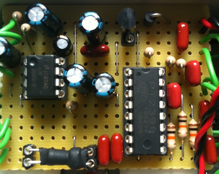
Here’s a vero layout of the Mid-Fi Clari(not). It sounds like a really fun little circuit.
Update (13.10.2011): Mod suggestion from Milkit: “Cut the trace joining pins 1 & 8 of the LM386, join them back together with an spst switch & you have yourself a fuzz cut switch. It doesn’t cut out the fuzz totally, but it’s not so prominent, kinda becomes more of an overdriven sound.”
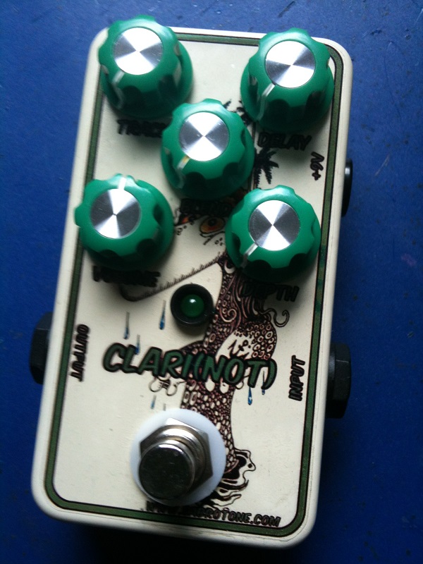
Update (06.08.2012): Finished this effect the other night and it’s really fun, but maybe not so useful. Those knobs needs to come off again, but other than that I’m fairly happy with it.
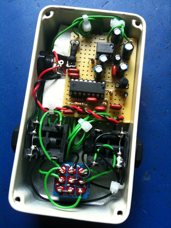


I have a finished board that I have completed and boxed up and the LED does light up. The rest of the circuit works fine, delay, fuzz, blend, etc.
I did test the LDR with a laser pointer and it does work, resulting in shifting of pitch of the sound. Is there part of the circuit I should focus on related to the LED? Pot? Cap?
Nice one, Erik. Regarding the delay pot I don’t know what way the original is oriented, but as you say it’s an easy thing to correct, so I thnk I’ll leave it like it is, corresponding to the schematic it was based on.
Hi Harald,
What a wonderful effect. Only thing is that it still has some fuzzy background noise in the delay when fuzz is turned off. Is this just the behaviour of this schematic? Anyways, it easily cleans up when I roll off the guitars volume, so no big deal.
When fuzz is engageer it sounds huge !!
Grat layout again. Thanks !!
Maybe one thing to change is the wiring of the delay pot. I don’t know what the original is like, but when it’s wired like this layout the delay control goes clockwise from long to short delay and the dept goes from a lot to no effect. I did it backwards, because it seems more logical to me.
Erik
It doesn’t hurt to try, but I’ve read that most LDRs respond preferably to light in the red spectrum. From own experience I’ve had most luck with red and orange LEDs when creating optocouplers.
Hi, Harald
I just set the components out and ready to build.
but somehow i wonder what if the LED for opto’s are combination led (changing color led) with ordinary 9200/9203 LDR.
Have anyone done this or have the clue for results?
thx.
rick, the LED/LDR is definitely a potential problem. These come in so many different variants it’s almost like magic. If it’s any help I think I ended up using the “9200” or “9203” $.95 LDRs from smallbear.
Hi, tried to make one but cant get it working properly. It works somewhat, but not all features. Is there anything special about the LED/R4 combination? Also, it there a schematic available, thanks
Thanks for the suggestion, kevtron.
I put an LED beside D2 to act as an indicator LED, doesn’t appear to drain voltage
The LM386N-3 should be just fine. As for the LDR I have no idea really; you should experiment, but either will probably work.
Very neat 🙂
Hi Harald,
Would a LM386N-3 be ok?
Which LDR would suit better:
Medium Light Res Dark Res
5K 1M
17K 1M
24K 500K
40.5K 1M
Thanks
Hi!
Have you checked the Deluxe version?
It has an extra Speed pot and LFO.
http://freestompboxes.org/viewtopic.php?f=7&t=4000&p=187248&hilit=clari+not+deluxe#p187248
I’m not that familiar with the PT2399 and you may be correct. I have built it with 10nF’s though, and it seems to be working just fine.
hi harald,
in this schematic: http://media.photobucket.com/image/mid%20fi%20clarinot%20schematic/midfielectronics/mid-fi_clarinot.png
is reported that the capacitors connected to pin 7 and 8 of IC3 are 100nF (and not 10nF)..
maybe there is a mistake?
thanks
Harald you should definately Build it! I only had a few minutes to try it out yesterday, but it´s the bomb!
Thanks for your reply! I really love your work, and can´t thank you enough!
I haven’t built this one yet, but I imagine you only adjust it so the effect as a whole “plays well” with your input signal. If this is indeed so yours is probably good.
I built it yesterday, and man it´s a very inspiring pedal!
Is the tracking knob very subtle? I barely hear a difference if i use it?!
Thanks and keep on rocking,
Chris
Another great layout, worked first time. Not sure i`ll use it overly much but a fun build and it`s there should i need it.Kudos to you
Another thanks for a great layout – works perfectly.
Hi, tunelion.
Have a look a bit further down on the layout. You’ll notice some additional wiring directions, particularly this one: “Volume 2 -> Output” indicating you should connect the volume pot lug #2 (wiper) to wherever you want circuit output to go.
Hi, i was looking the layout and you forgot to write the output.
Can you write it for me please?
thaks
Awesome! Thanks Harald, I’m ordering parts now and can’t wait to get started on some builds
Hi, Boxcar.
You’d make a cut at either e4 or e5. And if you look at my build pictures of, say the “Flatline Compressor” or “Baja Opto-Limiter”, you’ll see examples of LED and LDR sealed together with shrink tube.
I’m completely new to this stuff, but what is meant by “cut the trace joining pins 1 & 8 of the LM386”, what would the Alpha-Number corresponding points be on the diagram?
Also, how are D2 and R4 sealed together if they’re so far away on the board?
Sorry for the newb questions, just trying to figure this stuff out.
Thanks
Thanks for the suggestion, Milkit. I updated the post.
Hi just thought I’d let you know about small & simple mod for the “clari(not). Cut the trace joining pins 1 & 8 of the LM386, join them back together with an spst switch & you have yourself a fuzz cut switch. It doesn’t cut out the fuzz totally, but it’s not so prominent, kinda becomes more of an overdriven sound.
Loving this pedal though, so much fun! Thanks for the layout dude!
Thanks for letting us know, Chris.
This layout works great!!! Thanks a bunch!!!