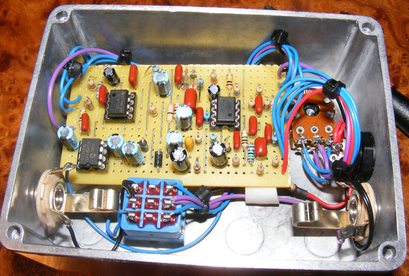
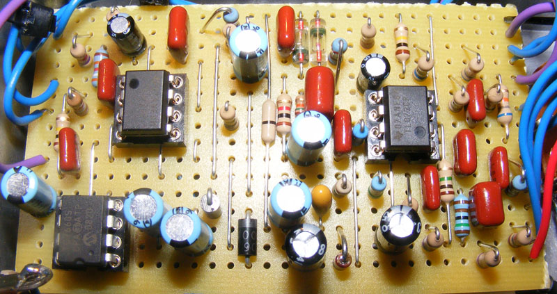
Here’s a layout I did for the Klon Centaur overdrive based on a schematic by soulsonic.
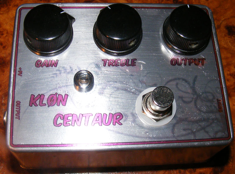
Update (28.02.2011): I finally got around to boxing the Centaur. This time I felt brave and decided to try an artwork technique courtesy of “frequencycentral” over at freestompboxes.org (described in this thread). I thought I gave it a good go being the first time and all, but needless to say from looking at the picture my only option was to leave it to dry outside in -20 degrees Celsius (that’s -4F for you Americans) and the result was less than optimal. Looking forward to spring and my next attempt.
Update (18.03.2012): I’ve had several requests for voltage readings from my build and here goes:
Battery at approx. +8.90v and all pots at zero.
| IC1 | IC2 | IC3 | |
|---|---|---|---|
| 1 | +4.43V | +4.6V | +8.84V |
| 2 | +4.44V | +4.43V | +4.52V |
| 3 | +3.45V | +4.43V | 0V |
| 4 | 0V | -8.44V | -4.13V |
| 5 | +4.43V | +4.42V | -8.42V |
| 6 | +4.43V | +4.43V | +3.97V |
| 7 | +4.41V | +4.26V | +5.29V |
| 8 | +8.87V | +15.92V | +8.82V |
I don’t know whether these are the “correct” voltages, but mine sounds good so…
Update (21.06.2012): Fixed an error on the layout where gain lugs #1 and #3 were swapped. Thanks to Dieter Brenner for pointing this out!


I think I figured it out.
For anyone interested in true bypass, I removed: R2, R6, R8, R11, R13 & C13
Everything works. Had to use the MAX1044 in IC3 to get rid of a high pitched noise.
Great sounding pedal. Might do the bass mod as it is naturally a more mid focused pedal.
Kind of a noob, Building this right now and would like to wire it for true bypass.
According to some other versions, I’m supposed to omit a “100k, 4.7uf and 1uf”
Can you tell me the location of these components on your layout?
Any help would be greatly appreciated. Can’t wait to finish
Thanks!
– Z
Thanks for answering, Nico. I’ve also got this info (and a bit more stuff) in the FAQ section.
Thank you vero much Nico!
@ Giorgio:
are you using DPDT or 3PDT?
for a DPDT the order is:
1 4
2 5
3 6
Can anyone help me about the order pin number of dpdt? On web i found two Ways to wire them and i don’t know which si right for this pedal. Thanks
Hello Harald, great informative site, thank you.
I just finished a build of the centaur andI get pretty strange readings on IC2 lug #4 and IC3 lug#5 (something like -3.5V instead of -8.4V).
Checking the board it seems to me those lugs on each of the ICs are directly connected to each other and to the 1uF cap (C22).
I used 1N4002 INSTEAD OF 1N4001 for D4 and D5. Any… leads I might try to follow..?
Thank you
I finished building this pedal today, and I am amazed! I’d never played a Klon (clone) before and was suspicious of the hype. I’d still never pay the crazy money for an original, but it really is a lovely sounding effect. Thanks for the layout Harald!
Thanks for the reply, looks you were right 🙂 Got it working now by replacing C3 and the 1M pulldown resistor, which i measured only 170 kohms instead of 1M. Finally boxed: https://s31.postimg.org/6mt3pe4bv/99myths.jpg
Made a little mod with the clipping stage and the 3.9nF-cap, so different diode types can be switched, and the different caps from 3.3 to 20nF for the bass/mid-tone response. awesome device.
Thanks again, great site, Harald!
Hi john,
Sorry to hear it’s not working as it should. Not too much I can do to help either, I’m afraid. Could the pops be due to a poor ground connection or faulty input/output caps?
Great layout, thanks Harald!
Sounds awesome, just one thing, I have pretty loud pops when engaging, also when I switch off. I have checked the circuit several tims, but I didn’t find any mistakes.
Hi Jonathan,
I have to admit I’m not totally understanding what is happening here. I’m thinking you’ve built the whole circuit horizontally mirrored, but you have to correct me if I’m wrong. Maybe it’s a case of different perspectives?
All my layouts are drawn as if the board is lying copper/strip side down, and with components mounted on the non-conducting side facing upwards. The copper strips and trace cuts can be seen on the layout as if the board material was translucent. I.e. when preparing the vero board you should flip it around, copper side up, and add the trace cuts mirrored.
Am I making any sense or is this a different issue altogether?
I’d like to make a comment based on my main mistake with this build..
When doing all of the layout and cuts, I had the trace side of the vero board facing me, and copied the whole layout but stuffing the components in from the rear, including the IC sockets! In doing so, the pinouts of the ICs were horizontally reversed.
So if you’re getting ridiculous voltages and 8.x vdc on pin1, your IC sockets need to be on the reverse side of the board.
Just an error I hadn’t seen anyone else mention.
Hi Spencer,
I have to disappoint you I’m afraid. I’m not sure what the problem might be. Have you checked your IC voltage readings against the ones I posted?
Harald,
Great layout – I built this and it sounds fantastic!
Except –
When the output is higher than about 50% and I move the gain to about 75% or higher, there is an underlying static or noise like it’s driven too hard or I’m getting noise from somewhere. Any ideas?
I’ve changed out the IC’s (all three of them) to no avail and now I’m tracing all the components.
If you have any direction for me on where to look, I would appreciate it.
Thanks, man – Great schematic!
Rodney, maybe this will help a little.
http://oi62.tinypic.com/o86r7l.jpg
Hi Harald
If I use a 3pdt stomp switch do I ignore the middle row (4,5,6) or the row to the right (7,8,9)?
dale
Rodney, see answer under the request page.
R5/R10, both 27k, should set the bias voltage (approx. half your supply voltage) that’s going to be used a lot of places, including IC1 pin #3. R9 is responsible for raising pin #3 DC voltage to this bias voltage.
You should read roughly +4.5V DC at strip “b”, left side (where “Gain 3” also connects). If it’s not you might have a related component shorted or something similar; solve that.
Any possible way to get a good diagram/picture from any of the successful builds? I’m having trouble with wiring the board to the hardware,gain pot, board to switch etc. Any help would be greatly appreciated. I have gone thru the board meticulously. It’s exactly as the diagram. Just need help wiring it up. Thanks!
Can somebody point out what are the components that could affect IC1 pin3 voltage? It´s kind of frustrating to randomly swap components in hope to find the suspect. Every component is in the right place, all resistors are measured, cap values checked visually and different IC´s tested.
…Just tried with a different brand of 7660S (IC3) but no differences in voltages or sound… So thats not the cause for low IC1 pin3-voltages. I´d really like to hear how, if anybody got that sorted.
Hi, I´m having the same problem like many others seem to have too that IC1 pin3 voltage is low. Mine is only 1.1V and the pedal seems to lack some gain. Pretty sure that there´s no building errors as I made two of these.
Has anybody ever got that solved?
Could it be a bad IC3 chip? I tried a few, but all from the same batch so maybe I should order some more elsewhere?
Happy to hear you sorted it out, Jeff 🙂
Ok, this turned out to be a very simple error or my part, I’m so glad it was nothing more. I had erroneously connected GAIN lug 5 to ground 🙂
… And wow, this pedal sounds unbelievable! I prefer low gain crunch so even at GAIN=0 & VOLUME close to 10 this thing produces amazing tones for me. It seems to add some amazing type of harmonics to the tone.
This might even beat my Zendrive and Sweet Honey clones.
Thanks Harald for a great layout!
Hi Harold, do you know if the caps C12 through C22 must all be polarized? I installed bi-polar caps and my IC1 & IC2 voltages are way off and the pedal sounds terrible. All I get out of it is popping and crackling, mostly when I pick hard. Same thing in bypass. I’m wondering if it has anything to do with the caps?
Readings with PS voltage at 8.61v and all pots at 0.
IC1 (this IC was soldered in, I ran out of sockets… maybe I killed it?)
1: 1.36v 5: 0v
2: 1.36v 6: 1.5v
3: 0.96v 7: 8.0v
4: 0v 8: 8.6v
IC2 (socketed, notice NEG voltage on PIN 1 ??)
1: -4.2v 5: 0v
2: 0v 6: 0v
3: 0v 7: 4.26v
4: -8.16v 8: 15.3v
IC3 (socketed, this is the only one that looks about right)
1: 8.6v 5: -8.16v
2: 4.4v 6: 4.2v
3: 0v 7: 5.6v
4: -4.0v 8: 8.6v
Then I would investigate the components, traces etc. in the vicinity of IC1. Those voltages doesn’t look right.
I just finished it… have a problem:
TONE and VOL POT works fine… gain not..It cause the sound get dark way up from 0 to 3/4 then it starts overdrive for the last 1/4 to end.
checked circuit 2 times and i didn’t forget anything… all things are allright!
Ic2 and Ic3 are allright…Ic1 has some issues…
PIN3 1.20V
PIN6 1.80V
PIN7 8.50V
and with gain at maximum
PIN3 still 1.12
PIN6 3.50
PIN7 3.50 Already changed R9 and C3..any idea? i’m getting mad!
Thanks man! I appreciate it.
You’re right about the Klon having non-standard wiring requirements. It’s because it’s a buffered effect, and not a standard true-bypass setup.
As for salvaging what you have now, maybe, but you’ll have to do a bit of thinking. The easiest would be to remove the true-bypass wiring and just set it up as per the layout.
I feel as though I may have used my minimal knowledge to answer my own question but I don’t yet trust myself as I am a novice builder.
I got the klon board populated and began to move on to the switch wiring (which I used http://tagboardeffects.blogspot.com/2012/02/offboard-wiring.html for my off board wiring. Worked perfectly for the Timmy I built not long ago). I got the switch mostly wired up when I noticed that the switch wiring specific to this project was actually on the layout. duh.
So, my question is, can I salvage this/leave it this way or am I going to have to undo what I’ve done and follow the layout exactly for the switch? If I can salvage it what would I need to do differently from the layout?
Yes, that looks like the correct pot, though they’re out of stock. You could also get them from smallbear, who seem to have them in right now: http://www.smallbearelec.com/servlet/Detail?no=736
As for the diodes I’ve heard that the 1N34A ones are pretty crucial to get the same tone, though that’s not to say you can’t get a great sound using other diodes. The reason it has to be these ones is because of the very low voltage drop (less than 0.3V). They shouldn’t be that hard to find on ebay, but make sure to check the ones you get for duds (in my experience about 9 out of 10 are good and the rest are dead). Sucks to add a dead one to the circuit; could take a while to debug.
Is this the correct pot to use for the gain knob?
http://ca.mouser.com/Search/ProductDetail.aspx?R=RV16A03F-10-15R1-B15virtualkey14860000virtualkey313-1100F-100K
Also, any suggestions for 1N34a replacements diodes? Would this sound ok with LEDs or do you really need the germanium diodes to get ‘that’ sound?
Those voltages look very similar to mine, s that’s goo at least. I can’t tell what the problem is, but if power suddenly drops a natural place to start would be the voltage converter (IC3). Do a closer inspection of the components in that area of the circuit board, maybe you’ve got a solder bridge, misplaced component (electrolytic the wrong way?) or something like it.
Using a poweradapter @9.06volts
the top TL072
Pin 1 = 4.47v Pin 8 = 9.04v
Pin 2 = 4.47v Pin 7 = 4.47v
Pin 3 = 3.45v Pin 6 = 4.47v
Pin 4 = 0v Pin 5 = 4.47v
The middle Tl072
Pin 1 = 4.47v Pin 8 = 16.31v
Pin 2 = 4.47v Pin 7 = 4.09v
Pin 3 = 4.47v Pin 6 = 4.47v
Pin 4 = -8.69v Pin 5 = 4.47v
The bottom ICL7660
Pin 1 = 9.05v Pin 8 = 9.05v
Pin 2 = 3.79v Pin 7 = 7.04v
Pin 3 = 0v Pin 6 = 4.6v
Pin 4 = -5.01v Pin 5 = -8.69v
And after a while when the pedal has crapped out, most of the pin values on all the IC´s go down to half of these measurements. And Pin 7 on IC2(TL072) goes down to -6volts??
Hi Vidar,
I have no knowledge of that layout, but it’s probably quite similar to the one I have here somewhere. I’m not sure what could be wrong, but consider checking the voltages before and after those 30 seconds, and also comparing with the ones I have posted (do mind that the component labels might differ since you use a different layout). Could help point you in the right direction if there are any anomalies.
Hi! im having some trouble with my klone build(the one on tagboardeffects.com). the klon clone starts to crap out more and more, and in about 30 seconds of use it is all crackling and popping noises. it works fairly well up to that point… its the same if the effect is on or off. i´ve built myself an audio probe but not sure where/how to begin with it. any help is apreciated
No, if you put two caps in parallel you add their values, same as resistors in series.
Thanks Harald. The parallel trick doesn’t work like with resistors then? I’ll read up on that.
Also, I found another source, a brick&mortar store even, pretty nearby. Will hit them up for the right values tomorrow.
You can use the 330n in both circuits, but it will change the frequency response, by how much I don’t know. Alternately you could use the 330n in parallel with a 68n for a total capacitance of 398n; pretty close, but it might be a bit clumsy when it comes to the physical size of these things.
Hi Harald, I’m coming up on building this, but can’t get 390nF/0,39uF from my supplier. Should I substitute C2 with 330nF or with 470nF?
Same question for the 5bandEQ, I’ll post a comment on that page.
Thanks,
Lee
Happy to hear that, Steve 🙂
Just went through every single part and found that I had 560K at R25 instead of 560R. I had put 560R in my first build, but somehow put 560K in my second build. No wonder I couldn’t hardly hear anything. They all came from the same mammoth bag, but I guess a 560K slipped in there. I learned my lesson to always use my MM and check the values no matter what the bag says. Thanks so much for your help Harald, and the layout. I’m gonna use one for a clean boost, and one for OD.
Heh, hard to say, but you could start by A/B-ing the voltages on your circuits (or use the ones I posted). This could help you narrow the search down at least.
I’ve built two of these, and the second one doesn’t work. I got the polarity on C17 wrong with an electrolytic on the first one, and I got the polarity right on my second build, but it doesn’t work properly. It has great buffered bypass, but hardly any volume. All the controls are working, but just barely any volume. Any suggestions? I can’t see a difference on either board, after checking the traces and reflowing some iffy looking joints, still the same problem. The first one works perfectly, haha.
You could of course wire it as true-bypass, but you might learn a lot more if you take the time and try to sort out the buffered wiring. Go over it another time and see if you can find where the problem is. If I had more time I’d do a wiring diagram specifically for this layout, but that’s probably not going to happen anytime soon, sorry.
Hi Harald, finally got around to putting this in a box but Ive it a problem. I lose the signal completely when I switch the pedal off, still connected to the power. I normally run my builds in true bypass & not buffered. Surely the signal should get through as long as the power is still on to the box? I think I must have the switch wired up wrong as when I just use a direct feed from the board at on/off sw2 to the jack it works fine. Could i just wire it up in true bypass on the understanding that the buffer will only kick in when the pedal is engaged? Id wire it up with the buffer if I could just figure out what going wrong the switching 🙂
I finished it yesterday (finally get one 4.7 cap). Awesome sound! Made with MAX1044 and 9.1V Zener, In case someone doesn´t find easily the 7660 like me.
Hi Roque. You’ll probably be fine replacing either one (or both) with a slightly larger cap, like 10u. These control the frequencies you output and the larger the value the lower the frequency threshold.
Hello, I realized I only ordered one 4.7uF cap. Can I change any of the 2 in the layout to other value? I this 10uF is the next value I have, maybe 3.3uF but not sur.
Thanks
I updated the layout, Andy.
Hi Harlad, just a quick couple of questions. Have you already altered the vero board to reflect Deiters recommendations & do you still need to connect A2 & B3 on the pot? Excellent layout dude.
Thanks a lot Harald…
I’ll try!
Being a circuit with multiple audio paths I don’t think there’s one single “tone cap” but quite a few of them, and I have no idea which ones to change really. I suggest reading up on the relevant threads over at FSB. As an alternative you could try to breadboard the whole circuit and start experimenting with cap swaps.
I’ve made the correction…
Before it was: WOW!
Now is: WOOOOOOOOOOOOOOOOW!
Thanks a lot guys!
Just a little question: can you say me which is the “tone” capacitor?
I’d like to put an DPDT switch to “switch” from these capacitors…but i don’t know which capacitor i’ve to substitute (or better make in parallel way).
Thanks a lot!
GX
Holy shit! Thank you SO MUCH for the gain pot correction!!!
If ANYONE out there built this originally and is having this unholy squealing when all the pots are turned up, THIS was the problem. I have been banging my head on this build for months and this was the solution. Thank you thank you thank you!!!
Yeah now that’s what time talking about. Sounds phenomenal
Now. Really fat!
I knew I wasn’t crazy! Haha awesome stuff guys!
Interesting. I think you just discovered an error on my layout! I’ll fix that right away. Nice catch, thank you 🙂
I solved my “muffled-gain-problem” as follows:
Connect the dual-pot (level A and B) like this:
Lug A1: Gain4
Lug A2: Gain5
Lug A3: Gain6
Lug B1: Gain3
Lug B2: Gain2
Lug B3: Gain1
Also connect A2B3
Now it sounds goooood!
Can’t be the pot. Mine works fine except for that muffled thing you mentioned. I measured my IC voltages and I also get approx +1.6V from pin3 on IC1. I’m sure I built the vero 100% correct, I went over it several times.
I’m really stumped here, don’t know what to do next, and I REALLY don’t feel like rebuilding the whole thing 😉
That’s the right lug numbering.
Luka, I have completely rebuilt the Klon because I did notice a few mistakes on mine. I am having the same problem with my gain pot but other than that it sounds good. When the gain is all the way off, it’s muffled, but as soon as I bring it up even the slIghtest, it’s clear again. Which makes me think the pot is wired wrong. I wired based on the 123 – top 456 – bottom with shaft up and lugs facing me.
I’m having the same issue as Josh. It’s safe to say that C3 is not the culprit, as I’ve tried several others and with other IC’s and with the same results.
Josh let me know if you’ve solved the problem and how 😉
Great news, Andrea! 🙂 I’ll consider adding this info to other builds as well, though it’s a bit of additional work.
Yes Harald, I fixed. Awesome.
The IC’s voltages is a good idea that you probably should inert in every pedal (from now on). it may be so helpful!
Thanks again
Andrea
Ok guys, i think i’ve found my definitively Overdrive!
This pedal is simply fantastic…no other words.
The circuit is just a little long to make…but the final wiring is simply and clear!
What can i also say?
Thanks Harald!
Thanks a lot!
You’re welcome, Andrea. Hope you’ll be able to fix your problem.
Harald,
thanks for voltages, I really appreciate it.
Very kind from you.
Andrea
I don’t know about the IC being bad, but it won’t hurt to try another if you’ve got extras. I assume you’ve gone over the circuit looking for short circuits like solder bridges and trace cuts not actually breaking the connection completely? Other than that there isn’t much I can do with the limited knowledge I have. Maybe consult the debug FAQ at http://www.geofex.com or the debug thread at the DIYstompboxes forum.
Just swapped c3. Voltage is still 1.56 on pin 3. You think the chip is bad?
c3’s value along with all the others are correct. pin 3 on ic1 is directly related to the gain right? thats where i’m having my problems. pins 6 and 7 on the charge pump ic are a little high by a volt or 2 but idt that would affect anything would it?
ill try replacing the c3 tonight and see if that changes anything.
You’re saying R9 is good, but what about C3? Maybe it’s leaky or bad? Just a thought.
Just tested voltages. The only thing off is pin 3 of ic1. I’m only getting 1.56. Te rest of my voltages were a consistant .20-.30 higher due to higher input voltage. Any ideas what could be causing this? The resistor immediate to pin 3 is correct.
The on/off switch lug #1 does indeed need two wires. The reason you only see one wire connected to the 3PDT is because I’ve daisy-chained the connection via the volume/output pot rather than the 3PDT itself, i.e. one wire from the 3PDT to the volume pot and then another wire from the pot to the location on the circuit board.
Hope you’re able to figure out the issue and get it working 🙂
I saw you answer regarding the on/off switch lug #2 having two wires going to it…
But about on/off switch lug #1, does it also have two wires, one from the board where marked and also from output (volume) pot lug #2?
I ask because in looking at the pictures of the guts of your build of the klon, it looked like there was only one lug of the 3pdt (seemed like lug #2) that had two wires going to it. Am I just not seeing the other lug with two wires?
The 1N4742 is a 12V zener and I think any 12v zener will do just fine here.
Hi all,
I can’t find 1N4743. Any alternatives?
Bye
s.
That sounds right.
Does J1 (input) goto the input jack tip? And SW2 to the output jack tip, then you just wire the sleeves to ground?
thanks!
Very hard to tell, but I’d start looking for a mistake somewhere on your board. A missing cut, a short, a missing component or a component of the wrong value (i.e. 100k instead of 100ohm etc). Be thorough and systematic, and a DMM helps alot. Sorry I can’t be of more help.
Idk this is like turning your guitars neck pup’s tone all the way down kinda sound. Otherwise everything works great. An I looked at my sheet and the cap I subbed was the 3.9n. I used a 3.3n. My C6 is a ceramic. But I don’t think that matters.
I count the ones closest to the shaft as 123, but it doesn’t really matter. Either way is fine as they’re both identical. What you could do is try another pot. Since most pots have a fair amount of tolerance, maybe +/- 10% you could, as far as I understand, theoretically have one of the tracks 90k and the other one 110k, which I imagine could throw things off a bit. To test whether this is the problem you could hook up two individual 100k pots and dial in the exact same resistance on both (use a multimeter) and see if that cleans up the sound. Just an idea.
Something is weird with my gain pot. When it’s all the way down its really muddy even with the treble knob all the way up. With the dual gang pot facing you with the shaft up are the lugs closest to the shaft 123 and the lugs farthest from tr shaft 456?
I’m pretty sure the 330p will work just fine 🙂
im sorry, i used a 330p instead of the 390p for C6.
I used a 330 instead of the 390 for C2, will that effect anything?
Ooops, ignore my last comment, it looks like I had the schematic from May 25, 2008 and not the corrected one from April 15, 2009.
Building this at the moment, nice layout. Looks like you might have a typo on C2, should it be 330nF instead of 390nF
Built this yesterday. Sounds amazing. A little bass heavy and my unity output is with the volume pretty much all the way up. Both might be due to my amp being channel jumpered though. Still sounds really good. Built mine with LM313h’s for the clipping diodes. I believe their silicon. Little
More gain than the original but love the tone. Awesome work on the layout. This was only my secon pedal build after completing a zvex SHO clone with an added volume knob. Worked first time I plugged her in. Used all metal film resistors tho.
Hi all,
Can someone satisfied with his result post the bias voltages on his ICs?
Please, I’d really appreciate your help
Andrea
Cool. Thanks!
I’m glad I don’t need to add one.
I havent built with layouts from your site…yet. Think I may give this one a shot.
That 7660 IC is a voltage doubler. A subset of the circuit is run internally on +18v.
Will this run on 18v? I believe the original does and I dont think I see a charge pump, but, as always, I could be wrong.
thanks in advance.
As Mark said you’ll probably be fine using 1N60s.
The germanium diodes all have similar voltage drops so you should not be able to discern any audible difference.
can i use 1n60 for 1n34a ? is there any suond differences?
Please…..
🙁
Andrea
Ok, so me and Sean need ICs Bias point… 😉
Andrea
Hi there, my build also sounds crap, shame because the box looks great. Any advice likewise appreciated.
Thanks for the layouts Harald.
Thanks so much Harald!
😉
Andrea
Hi, Andrea. I don’t know where my build is at the moment, but I’ll post voltage readings if I locate it. And I don’t think the exact resistor values are of critical importance.
Noone?
Please!
Merry Christmas and happy new year!
Andrea
Hi all,
I made this pedal work, but it sounds crap.
Can someone satisfied with his result post the bias voltages on his ICs?
I also could not find the two values 392k and 422k… could this be a problem?
thank you so much everybody, and Merry Christmas to you all.
Andrea
Hi, Andrea. It’s been a long time since I had a look at this circuit, but wiring the Klon as true-bypass shouldn’t be a problem at all. Just ignore the bypass output and treat the effect output as a regular circuit output, then wire as you would any regular true-bypass build.
As for vero submissions I appreciate the thought, but I’m going to have to pass, at least for now. I already have so much going on and it would be hard finding the extra time.
Hi Harald,
it would be nice to complete this Vero with True Bypass version and the suggestion for different Germanium diodes (both suggestions under MadbeanPedal SUNKING).
Cheers.
PS: If I have a vero to submit, where can I post it (if you are interested)?
It’s been a while now, but I’m fairly certain I was able to source most of it from http://www.mouser.com.
Hi,
did you find all suggsted components? Even 422K and 392K resistor? And what about caps? It’s almost impossible to me to find all Panasonic ones.
Thank you
Andrea
Thanks for the advice man… I might put this one on the back burner for a little bit. Ive had all the Klon I can stand for now.
Hi, Jacob. Sorry to hear you’re having problems. Have you checked for shorts? You may want to go over the entire board using a DMM with continuity check and make sure no two tracks are bridged (unless there’s a deliberate jumper of course). My next suggestion is to get a copy of the schematic (I believe you can still find this at http://www.freestompboxes.org), build an audio probe and start following the input signal as it travels through the circuit from input towards output. You’ll have to cross reference the schematic and the layout and it won’t be easy, but this can be really valuable in narrowing down what region of the circuit is having problems.
Hey Harald,
First things first… great job on the veros and your site. By far one of the best ive seen on the web. Thanks for all you do!
Here is why I am commenting-
I built the Klon. It isnt working for me. I did it on perf board but i know i made all the cuts/links. I double checked placement to make sure I didnt miss anything.
I also checked my pot and switch wiring. Everything I can think of. (when i say checked, i mean for the past 2 weeks ive looked at this thing)
SO this is what i have: When its on I get a hum but no input. when its off, I get no bypass. So im not sure what to do. any advice?(I also swapped out the IC’s in case they were bad).
Hi Harald,
problem solved. Thanks
Hi, Ben. It’s a bit hard to say as it could be caused by a lot of things. I really recommend you visit http://www.geofex.com and check out the debug section (link in the top left corner); there’s a section in particular dealing with getting your effects to work for the first time. That’s where I’d start if I were you. Hope that helps.
Hi Harald,
I have done the klon and I have a little problem, it is very noisy. A big hum is coming out of my amp when I switch the pedal on (my amp is dead quiet with other OD pedals). Do you have any idea what could be the problem?
Thank you .
Ben
Have a look at my switch numbering illustration in the “schematics & drawings” section. Yes, “on/off 2” goes to the output jack tip. In other words, you connect two wires to lug #2 on the switch, one goes to the board as indicated and one goes to the output jack.
Harald i need help. Hw is ur on/off switch numbering on the layout correspond to the 3pdt i have in hand nw. im confused.
Also, on/off switch 2 >> output (signal) means connect it to my output jack??
Hi, Henning. If I’m getting your question I think you’ll find the answer under the “Schematics & drawings” page. They’re not pretty, but I added a pair of pictures showing how I number the lugs on the switches and pots. As for the 3PDT with the Klon build, since it’s a buffered effect you can get away with using a DPDT. You can still use a 3PDT; you just leave one of its poles unused.
Hello Harald
first I have to say my deepest respect for your work. I recently built a lot of your vero designs and Iḿ very happy with finding my golden tone. Especially with the OKKO. I just finished building the Klon but I have several problems. I compared different layouts and veroprojects. I use a 3 DPDT switch. And how is the layout there? The dual 100 k pot is my second problem. You connect Gain 1 to Gain 5. That means Gain 1 is normally the Ground Connection of a pot with lug 2 of the second stage which is normally the output lug. I think the mistake is just right between my ears!!!! Would you please help me??
Henning
Second one.
HI Harald,
How do you wire the dual pot ?
1 2 3
6 5 4
or
1 2 3
4 5 6
Thanks
Looks pretty good to me. I’ve used water-slide decals for a while now, but they’re too brittle. I’ve always wanted to attempt the inkjet transparency film method.
How’re you liking the Klon Centaur? I built a clone shortly after it was first traced. Loved it then, but now I scarcely use it. Oddly enough, the Okko Diablo has taken it’s place as the go-to overdrive.