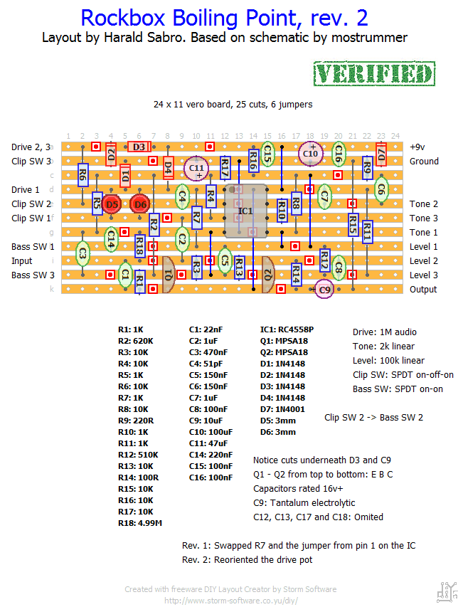
Looks like a pretty straight forward TS variant. I chose to omit most of the extra 100nF filtering caps to make the layout a bit smaller. As always let me know if you build it and it works 🙂
Update (02.10.2011): Just noticed and corrected a small mistake (moved R7 and a jumper).
Update (04.12.2011): Fixed the drive pot which had to be reoriented. Built this tonight and it is now verified.


You can use your typical polar electrolytic caps too, but you will have to figure out what way to orient them: Measure the DC voltage on both points of connection, then solder the electrolytic with the (+) leg on the more positive DC side.
I’m curious about the 1uf caps. This is the first (granted, of only a few) pedal I’ve built with non-polar caps of this value. Is this because the voltage oscillates in this part of the circuit? Thanks in advance for helping a beginner.
Hi Alex. Check out the “Wiring” section. Almost everyone uses one form or another of what’s typically referred to as “true bypass”. You’ll find my preference as the “regular true-bypass”. Good luck building! 🙂
Hey Guys,
This will be my first pedal build and I was wondering what peoples preffered method is for the implementation of an ON/OFF switch. I was thinking of using a double pole switch with one pole making/breaking the 9V supply and the other pole switching between the effect cct and a straight through trace inuput -> output.
Nope, that looks correct. Asymmetrical clipping; one diode drop vs three diode drops depending on the direction/polarity of the signal 😉
The easiest would probably be to change the Volume pot from a 100k linear to a 100k audio taper.
Hi Harald!! The clip switch 3 shouldnt be on d1 instead of b1???
Its now in th middle of the 3 diodes.
Hey Harald
How can i reduce the loudness in the level pot
in a way that i have the same level at half clockwise instead of quarter clockwise? For having more control with the effect on.
Sounds good, George 🙂
hi…here is a demo of this. With Haralds layout!
http://www.youtube.com/watch?v=P7aSZhbwn1k
Hi Vladimir. It doesn’t matter whether you use 3mm or 5mm. The original probably had 5mm ones, but there should be no electronic differences between the two, only a difference in the amount of transparent plastic surrounding the diode. 3mm is nice to use because it takes up less space, but if you intend to panel-mount them for a visual effect you may or may not like the looks of the 5mm ones better.
Does it matter if I use 3mm or 5 mm led diodes.Your layout says 3mm and this schematic says 5mm
http://1.bp.blogspot.com/-EmJBiuAbfE0/TwoN8p7ZppI/AAAAAAAAAbA/T8SrIhVf_Tw/s1600/2q9cl4x.jpg
Thanks in advance, love your work.
It sounds to me like what you’d typically see in high-gain builds. I believe it’s called parasitic oscillation, but don’t quote me on that.
There’s a number of rules you should follow when wiring high-gain pedals and if you search the forums you’ll probably find lots of discussions on the topic. In short, keep input and output wires separate as much as possible, keep all leads as short and direct as possible, cross wires at 90 degree angles and consider shielded wire for input and output if necessary.
hi Harald,
First off – many thanks for this site. I haven’t posted before but I spend tons of time on here. I have a question/problem. I built this pedal and everything seems to function as it should on one clip switch setting, but on the other two, when the drive pot is anywhere from 3/4 to full on, I get squeals and oscillation so strong the guitar signal will not pass through. I realize how this sounds – noise when you turn the drive all the way up??? Duh! but it’s not feedback I’m getting. it basically squeals and oscillates even with the guitar volume all the way down. Is this common, or have you ever heard of this happening? the one setting that doesn’t do this, is when I put the switch in the position with the lowest output volume. I’m new to pedal building, but I have checked for bad solder joints and for shorts and everything “seems” to be good. I was wondering if a bad component could be the culprit. very possible that I got something too hot while soldering… thanks for any advice you can offer.
Very cool 🙂
Hello just thought i shear i picture of my rockbox boiling point built by using Haralds vero layout
It works nice and is a very flexible overdrive
heres the link to pic
http://dl.dropbox.com/u/6927706/Photo%202012-05-09%2007%2019%2036.jpg
Sorry to hear you’re having problems. I’d put my money on a bad solder joint, a small solder bridge or a trace cut that’s still conducting. Look over everything closely and systematically.
Hi Harald
I have a question for you if you dont mind. Iv built the rockbox using the vero layout above.
It works fine except for one thing. The tone kontroll dosent work, it seems like it is none existing.
If you turn it down it seems like the entire circuit gets throug and then turning it clockwise nothing happens until you reach max all sound vanish. I then changed to a new pot and cecked my wiring. But still the same phenomen but now when turned down it dosent let everything throug but nohting happens untill max and all sound disappeares. What do you think? It is the cond, in the hipass or lowpass fliter that is broken ? Or what
Ok thanks again
Yes, the JRC4558D will work just fine as will most other dual opamps with the same pinout configuration (most of them).
Hi Harald
Iv just started collected parts for this build and im having a real problem getting hold of the ic rc4558p.
Would you be abel to use the standard jcr4558d instead? Or is there another ic that would be simiular?
Ok thanks again
Thanks for letting us know. Excellent news 🙂
Hey guys, this is just a post to let you guys know that the Boiling Point Vero is 100% identical to the real thing. We compared this to a real one and its perfect. Definitely beats paying $310 for a great pedal.
Hey Harold, i re-built this and got it working, don’t know where I goofed the first time, I think I will replace the leds with Fets, just to give it a bit different sound. I’m going to stick it in one big enclosure with a ts9 i built.
I hope you take pictures of your next amp build. Which one a you trying?
I am starting a build a firefly amp, found a real nice sounding 8 inch speaker made in 1963 (huge magnet). Just waiting for the big caps.
Sometimes a complete rebuild is the easier way to go, I do it sometimes.
And yes, the DIY amp is the only one I have. I built a 1X12″ speaker cabinet to match and it’s the only thing I use. I do, however, have another amp planned 😉
I havent had abuild in a while where i wanted to pull my hairout.
Harald thanks for verifying this,
I cant find where I goofed so, i’m going to start again.
Its funny though, my way it still works, but the tone sweep is weird, so like i said, i’ll start over
Cheers, Harald. Oh I was curious do you play alot on your DIY amp, or do you have another as your main piece.
Hi, Jacob. I’ve never tried an original unit, but it’s pretty much part for part a TS-808. There’s a few slightly tweaked components, but I can’t say if it’s for better or for worse.
How do you think it compares with the actual? is it really close?
Guys. This layout has been bugging me for a while so I decided to build it tonight just to find out what’s wrong. You were right about the pot wiring, but other than that the layout worked exactly as expected (and no jumper at c24-d24 either). Make sure you’re using rev.2 of the layout and you should be good. If you can’t get it working start looking for missing cuts, solder shorts, missing/misplaced components etc. I used a pair of MPSA18 transistors, but I also verified this works with 2N5088.
Hey Glenn, glad you tried it! After the corrections are made, and I receive more funds for my pedal building obsession, I think I will give it a try as well!
Harald,
Your site is awesome. I definitely thank you for all you do here!
This pedal is very loud and i attributed to the the “big” 6M9 resistor, making it very loud, but because I still am learning, maybe the pedal is just really loud.
Also about the extra jumper to get it to work, I don’t have a breadboard to really fool around with the cct too much, so if someone or you can try it out and “really verify it”. But with the jumper the pedal sounds great and all the pots function as they should. Thanks, Glenn
Thanks for the feedback, Glenn. I agree on the drive pot wiring and I’ll change it. But what do you mean by 6M9 pull-down resistor being too loud?
Hi, Harold I forgot to mention, I ran a jumper between row c-d on the 24th slot, otherwise i coulnt get the cct to work. The schematic at FSB i couldnt get a clear picture but it looks like your layout.
I checked my layout about 10 times and cant find where I went wrong, but with the extra jumper, the effect works….maybe someone built this and can chime in.
Hi Harald i just built this last night, after seeing Jacob was surpised that no one built this.
I didnt have any mpsa18’s so i used 2n5088’s and I am going to try some bc10x’s.
I also didnt gave a 5 meg input resistor, but i did have a 6.9 meg. TOO LOUD.I will solder 2 smaller resistors in series and try that.
I built a dynamic overhype before but it sounded ~cold~ to my ears even though this only has a couple extra caps,this thing sounds warmer to me, a keeper i think. (unless the is a blues driver out there somewhere.
Also, the drive pot…i wire all my pots according to your instructions, and this one is just backards. I wired the pot the other way and now and turns clockwise more gain…Again Harald, good job as always, i find myself going to this site before the other site now, just cause vero layouts per Harald RULE.
Im surprised nobody has tried this yet.