Building the Systech Harmonic Energizer vero, step by step
The following step by step guide attempts to describe how I go about creating a DIY guitar effect stomp box from start to finish using one of my vero layouts. It’s meant primarily as an aid for people just getting started. Hopefully it’ll be of some help.
Part 1: Preparing the vero board
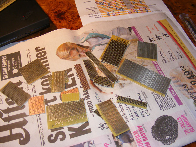
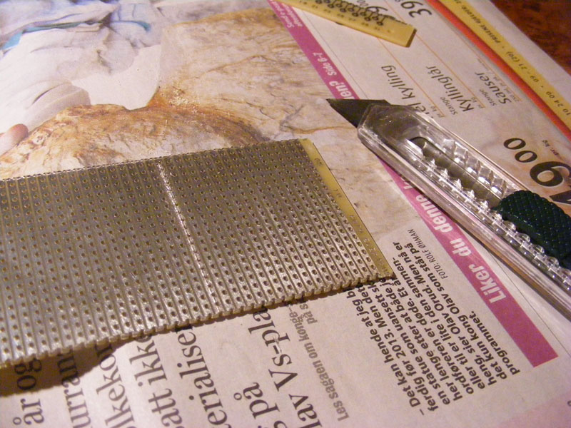
1. I’m preparing a vero board for the Systech Harmonic Energizer using this vero. Start by finding a suitably large piece of vero board you can use. This time I didn’t have any lying around so I had to start on a fresh one.
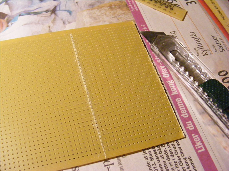
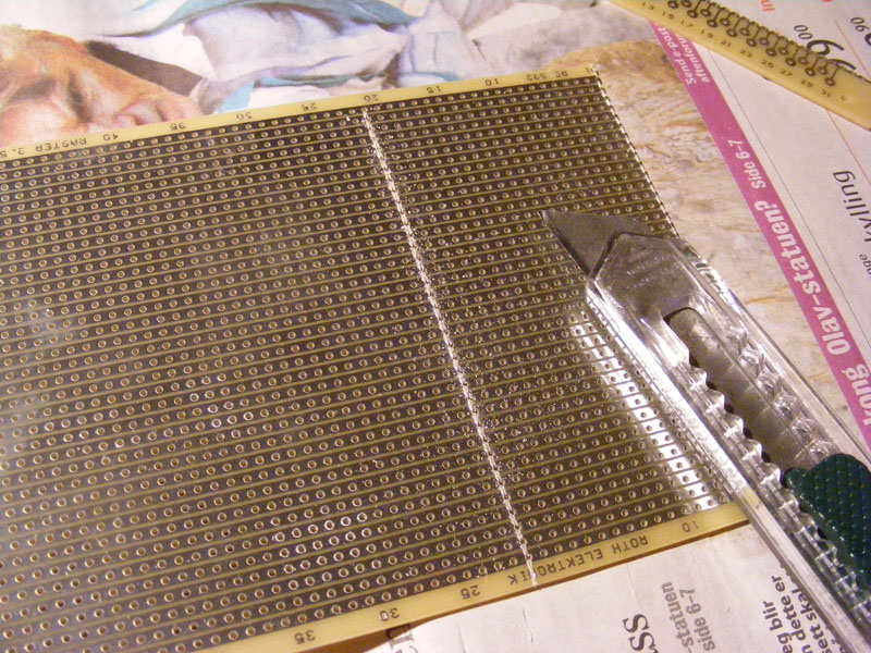
2. Determine the required size of the vero board, count everything a second time just to be sure, place a sharp knife on the next row and cut along the pre-drilled holes. You don’t need to cut all the way through, but you need a reasonable cut down the entire length. Now do the same thing on the other side of the board (make sure you cut along the same row of pre-drilled holes). Gently break the vero board along the cut (placing it on a table edge or similar could be helpful). In my case I needed a 19 x 16 vero board so I cut downwards across the vero strips at the 20th row of holes to give me a vero board with vero strips of 19 holes.
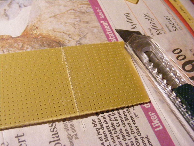
3. You’ve got a vero board of the correct width, but you also need to cut it to the right height. Follow the same procedure as in step 2. I needed 16 strips of vero so I cut along the 17th vero strip.
4. You now have a vero board of the correct size. Using the same knife I like to trim the edges of the board removing any rough spots left after breaking the board, but this isn’t strictly necessary.
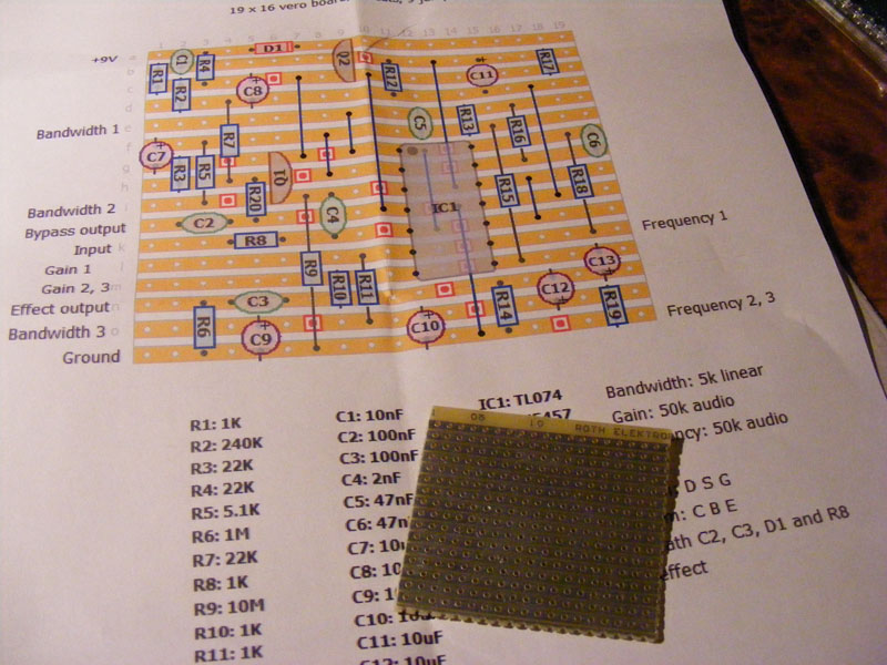
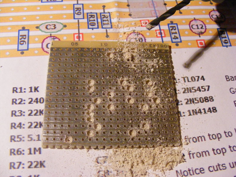
5. Next you need to make cuts in the vero strips according to the layout. There’s a good number of ways you can achieve this, but I like to use a drill bit. You can carve out a cut manually by spinning the bit between your finger, or you can use a Dremel or similar tool to get the job done much faster. I wouldn’t recommend you drill a hole through the entire board. Just shave enough off to break, or nearly break, the connection of the vero strip.
NOTE: The vero layouts are drawn as you would see them from the top with the actual vero strips on the under side. The cuts, however, are shown as if you could see through the board material. When it’s time for you to make the cuts you (obviously) need to place the board with the vero strips facing up, and view this way you mirror how you add the cuts compared to the layout.
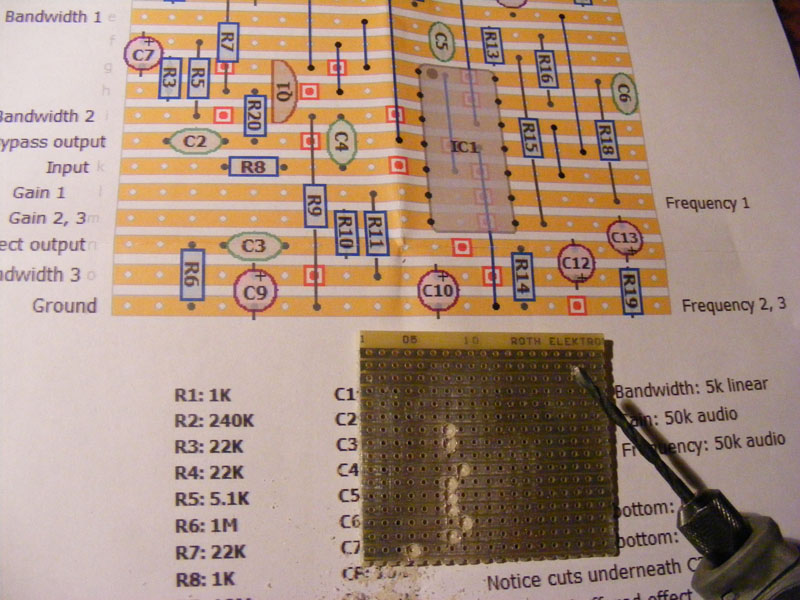
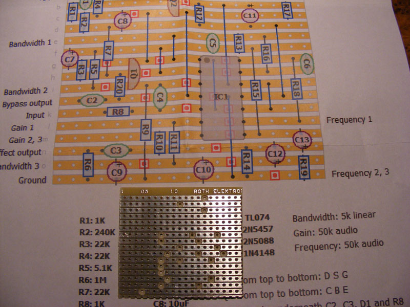
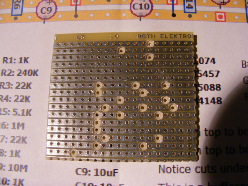
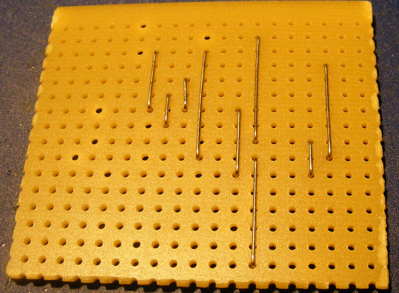
6. When all rough cuts are in place I go over each and every one of them with my knife and carefully clean them up. You don’t want any stray metal shavings shorting out two tracks. You can see in the picture how I’ve cleaned up the right most part of the board.
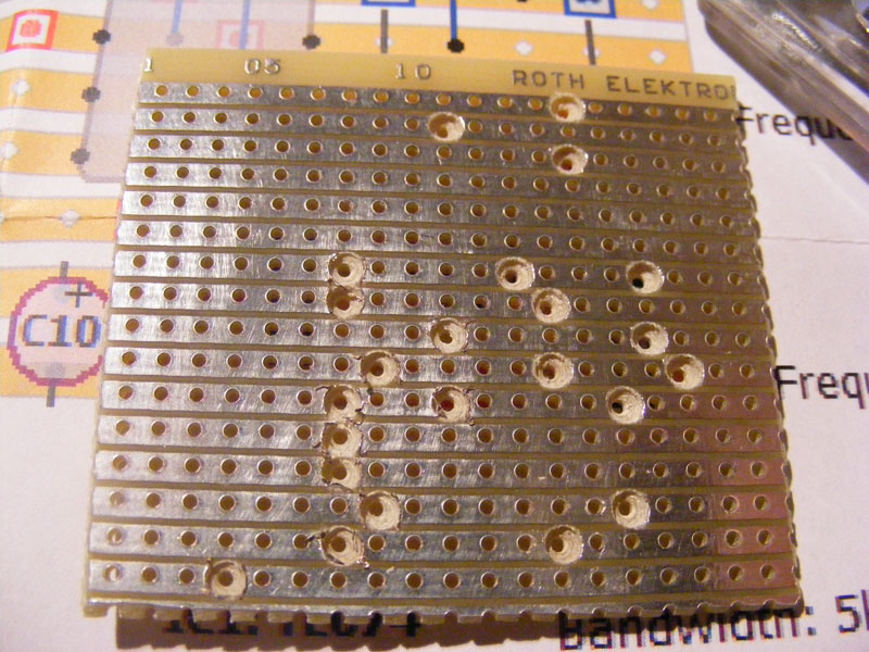
7. When every single cut has been cleaned up the board is essentially finished. Unless you’re 100% sure of your cuts now is the time to get out your multimeter and use the continuity test to verify each cut. This can save you a lot of time debugging.
Here’s my finished board. The next part of the build will be adding the various components that make up the circuit.
Part 2: Populating the vero board
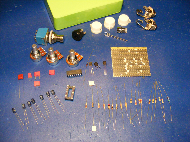
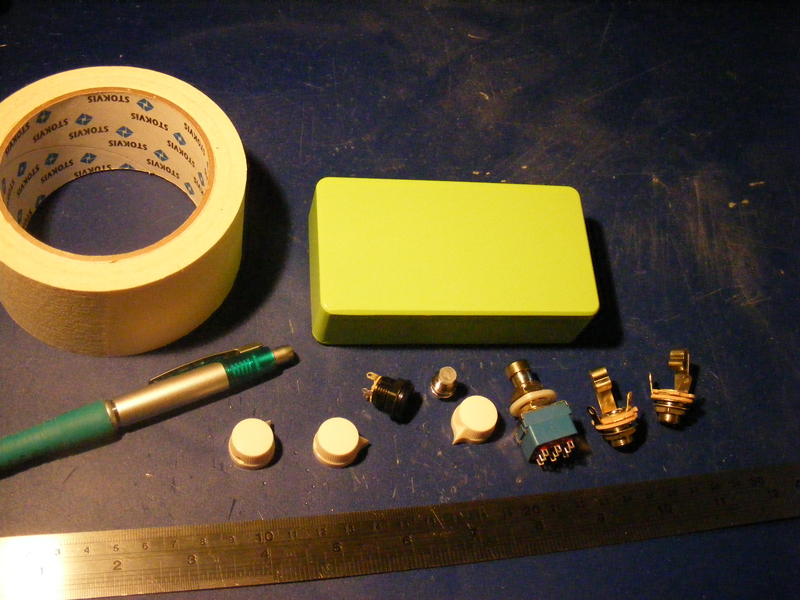
8. When it’s time to put together a working circuit I like to start off by making sure I have every part I need readily accessible. I usually have several projects ongoing at any given time and by putting aside the various components as I source them I don’t accidentally end up using any of them on a different effect.
If you’re really observant you’ll notice I haven’t been careful enough as there’s several parts missing (a 10k and a 5.1k resistor, a 47nF capacitor, and two transistor sockets), I got the wrong taper on the 50k pots, and I’ve got a spare transistor.
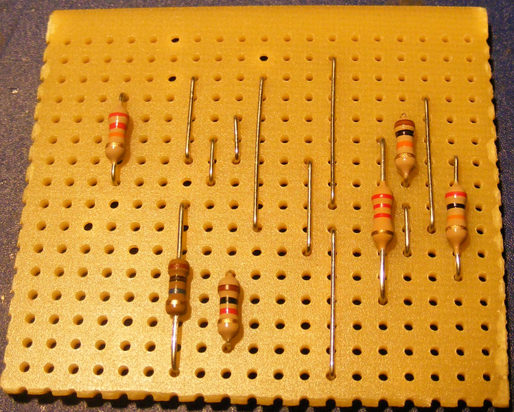
9. Turning the vero board around I make sure I’ve got it correctly oriented with the cuts now positioned as on the layout. I like to add components according to their height profile so the jumpers go first (I find it a bit frustrating to add jumpers at a later stage, and you must add them before any IC sockets that go above them). I use zero ohm resistors, and if I can get away with it just the legs, but the legs of any resistors will do. If a resistor leg isn’t long enough you can use the full zero ohm resistor or a length of regular wire.
10. Next I add any resistor and diode that can be placed lying down. This is usually the case with resistors that span four or more vero strips.
I would have added R5 (5.1k) as well, but I realized I didn’t actually have any so I left that problem to be solved later.
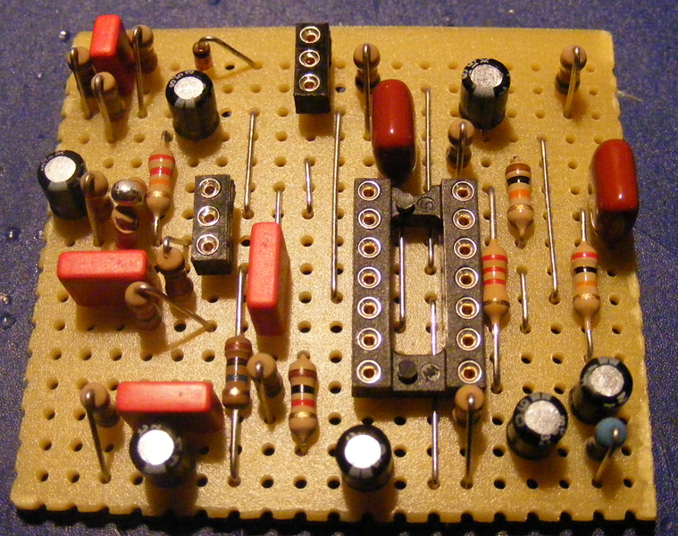
11. Here I add the transistor- and IC sockets, and the electrolytic capacitors. Electrolytes are usually about the last components I add, but the ones I used here had a really low profile.
Make sure you double- and triple check the orientation of the electrolytes!
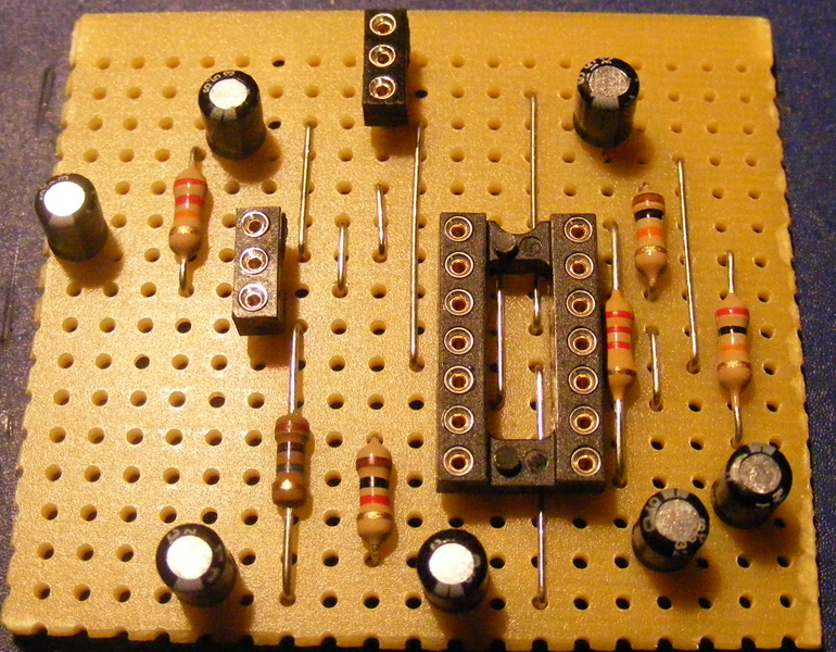
12. The next components on are the capacitors. For this project I use Wima film caps. I try to stick with a single type of capacitor if possible, but this time I didn’t have any 47nF ones and substituted a pair of Panasonic film caps instead. You’ll also notice I’ve added the diode which in this case had to be standing since it didn’t span enough vero strips.
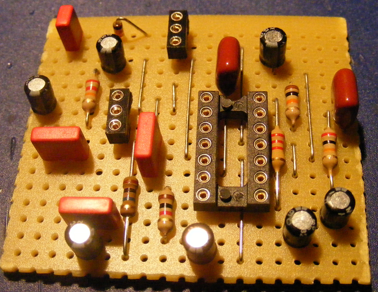
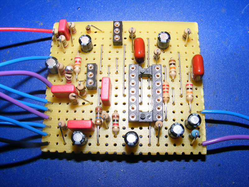
13. The last few components to be added here are the standing resistors. I also solve the problem of the missing 5.1k resistor by soldering together a 3.9k- and a 1.2k resistor in series.
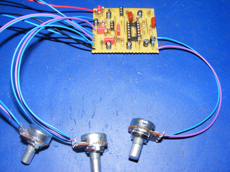
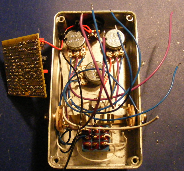
14. We’re almost done with the circuit. All that remains is the wiring and the pots. At this point I’m not too concerned with the length of the wires as these will be trimmed down when I later put everything together in an enclosure.
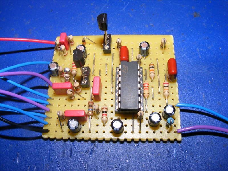
15. Since I used sockets adding the IC and the transistors is easy. The sockets serve a dual purpose; they protect these sensitive components from excessive heat from the soldering iron, and I can easily experiment with substitutes if I want to.
Be sure to observe the pinout of the transistors and the orientation of the IC!
The circuit is finished, but I really like to make sure before I proceed so I hook it up to a test rig and give it a try. If you don’t have a test rig you can always wire things up manually using alligator clips or something similar. The important thing is that you make sure everything works before you start on a permanent enclosure.
Part 3: Preparing the enclosure
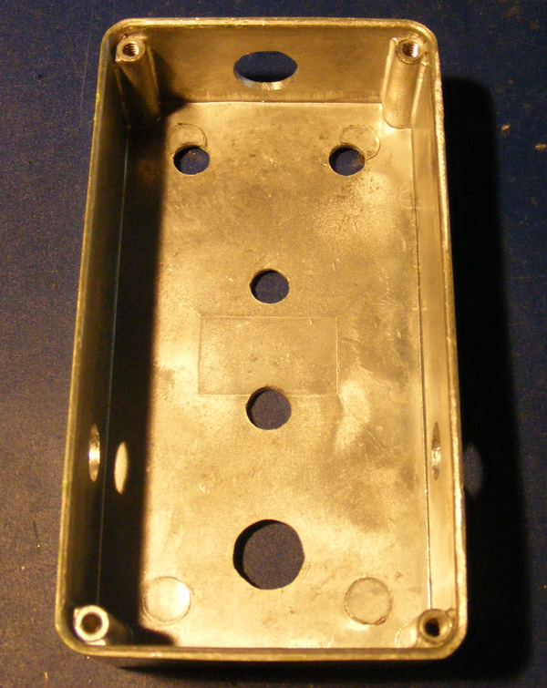
16. The enclosure needs to be prepared for the final assembly stage. Holes need to be drilled for the various hardware; input- and output jacks, stomp switch, indicator LED, DC jack, and all the circuit-specific controls (in this case I’ve got three pots).
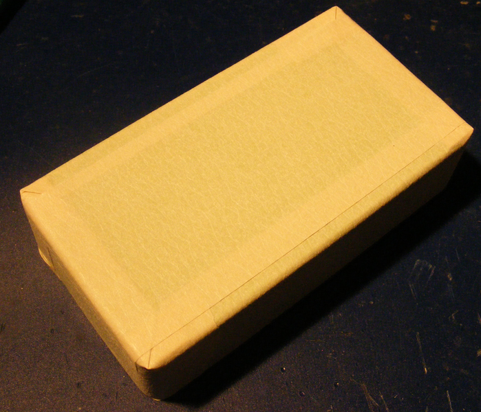
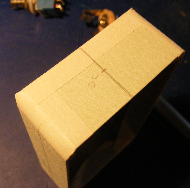
17. Culturejam of freestompboxes taught me this neat trick. I start by covering the enclosure in masking tape. This enables me to make measuring marks using a pencil without damaging the enclosure finish at all. It also helps protect the finish from accidental scratches when I later start drilling.
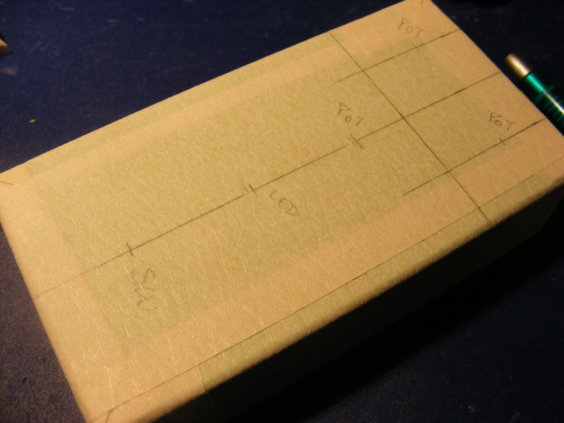
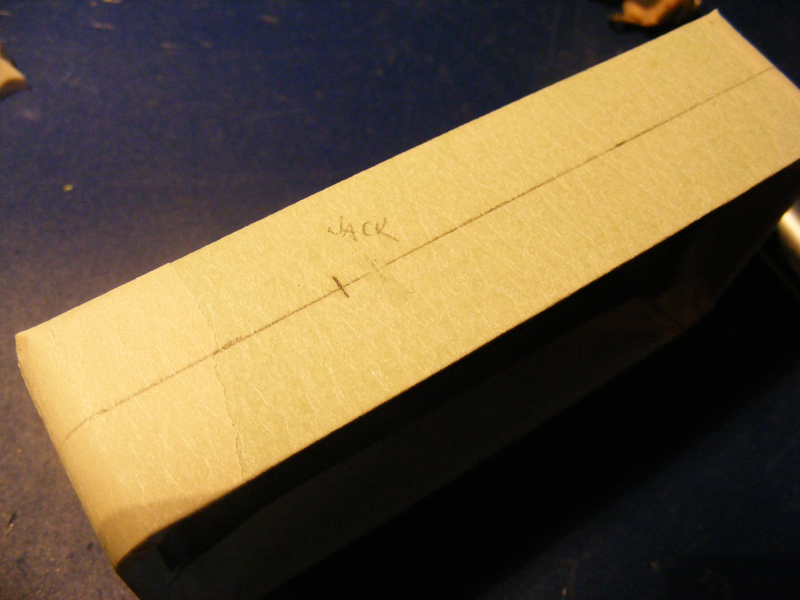
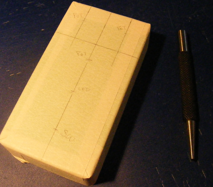
18. After having tried a few different placements I’ve decided how I want the box to look. I’ve made sure the input- and output jacks stay clear of the stomp switch and indicator LED, each pot and knob has adequate room to turn, and the DC jack on top of the enclosure fits nicely between the topmost two pots.
19. To be honest I’m not sure what this tool is called in english, but I use it with a hammer to carefully create a dent in the enclosure at the center of each hole I intend to drill. This helps to keep the drill bit in place as you make the crucial first holes.
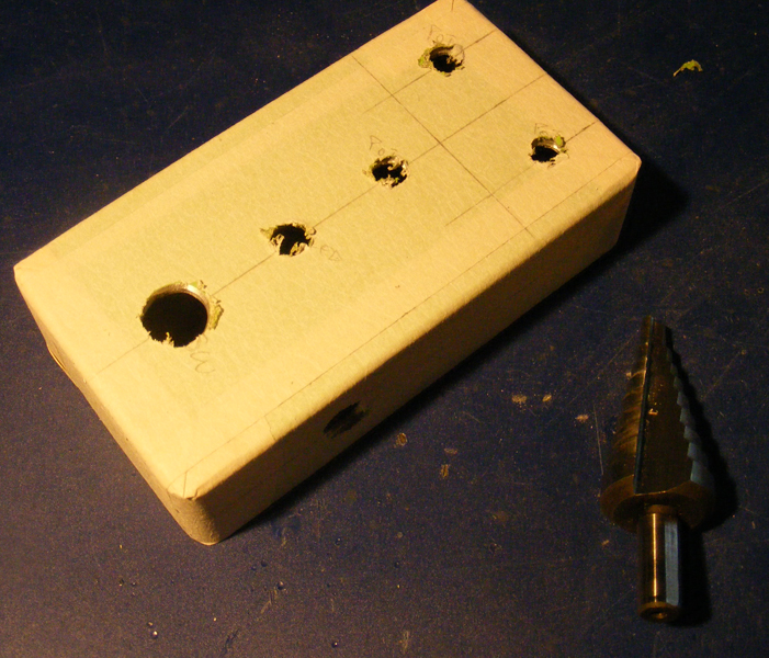
20. I always use a small drill bit (1.5mm) to start every hole, and move on to increasingly large bits until I’ve got a hole of the required diameter. I’ve found that it actually takes a lot less time to drill each hole in 3-5 stages rather than moving right to the large bit.
I’m using Alpha 16mm pots which requires 7mm holes, my LED bezel needed 8mm, and the Switchcraft input- and output jacks fit 9.5mm holes.
For the stomp switch and DC jack I had to use a conical drill bit to get the right diameters (12mm for the switch and 12.5mm for the DC jack).
It’s also a good idea to make sure the hardware actually fits.
21. After dusting off the metal shavings and carefully removing the masking tape the enclosure is ready for assembly.
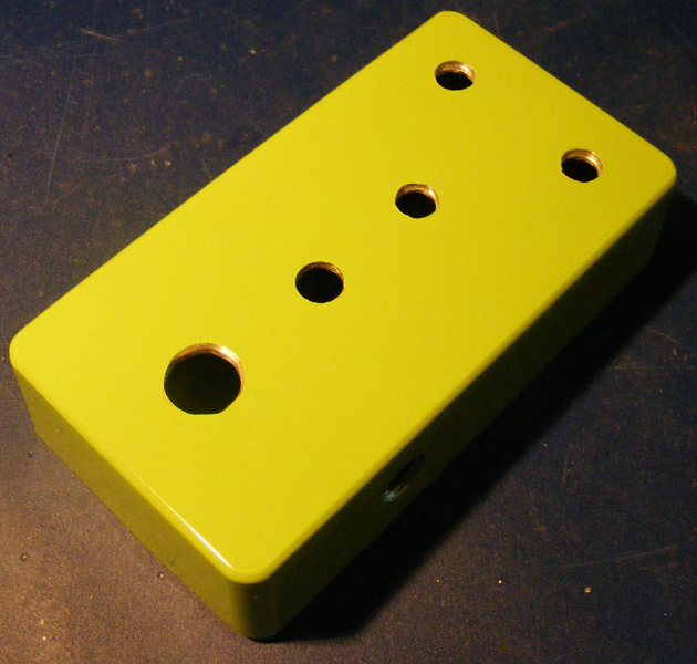
Note: This would be a good time to decorate the enclosure. I have very little experience with this so I’ll skip it and come back to it at a later time.
Part 4: Putting it all together
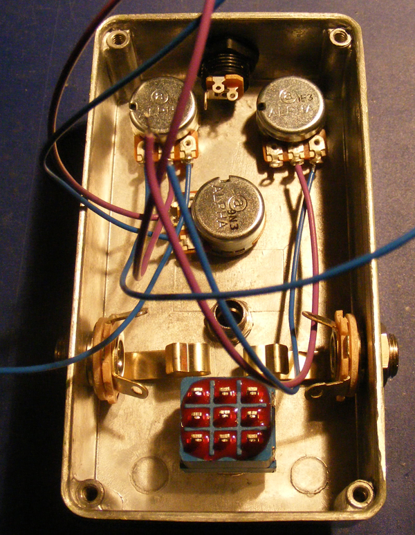
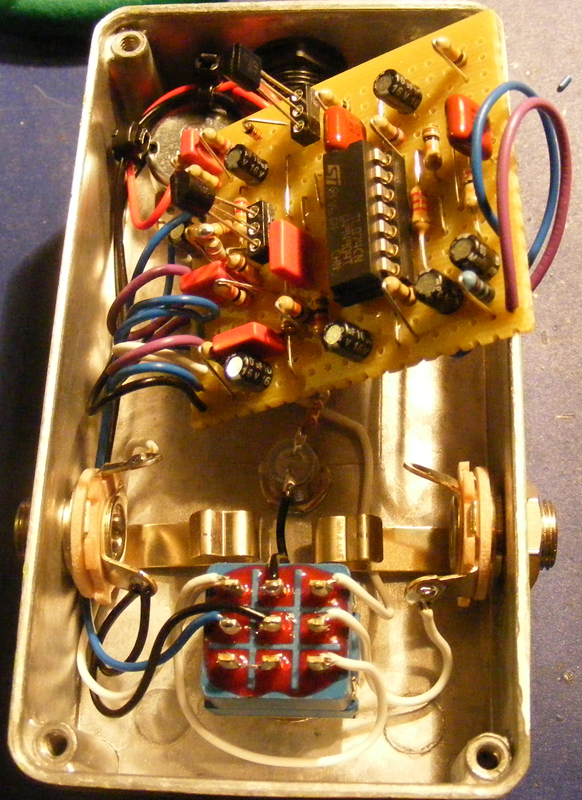
22.I’ve detached the pots and the wires from the board. I’ve also attached all the hardware to the enclosure.
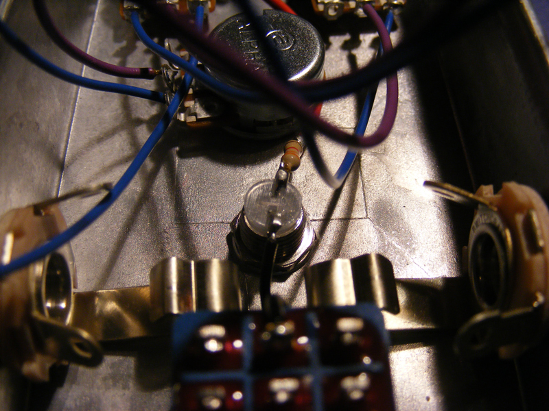
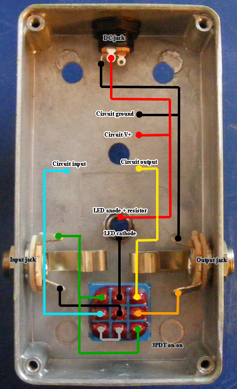
23. Here’s a closeup of the indicator LED. I’ve soldered a 3k3 resistor to the anode/positive side of the LED, which is again wired to the DC jack. The cathode/negative side of the LED is directly wired to lug 4/upper middle lug of the 3PDT. Notice the DC jack having three lugs. The left-most goes to the DC jack pin which usually goes to ground, and the top-most of the other two lugs is always connected to the DC jack sleeve which usually goes to +v. The last lug (the right-most) connects to the +v lug when no DC jack is inserted, but is disconnected if you insert one.
If want to also include a battery snap you typically want to use a stereo 1/4″ input jack, connect the battery snap ground wire to the input jack ring, and connect the battery snap +v wire to the right-most lug on the DC jack, the one that disconnects when a DC jack is inserted.
24. I’ve wired the 3PDT switch for true bypass. The effect actually has an input buffer and can be wired as a buffered effect, but I wanted to illustrate how I usually wire an effect. And there’s no harm in wiring a buffered effect as true bypass in my experience.
At this point I got fed up at taking poor quality pictures for every wire and decided to draw a wiring diagram instead.
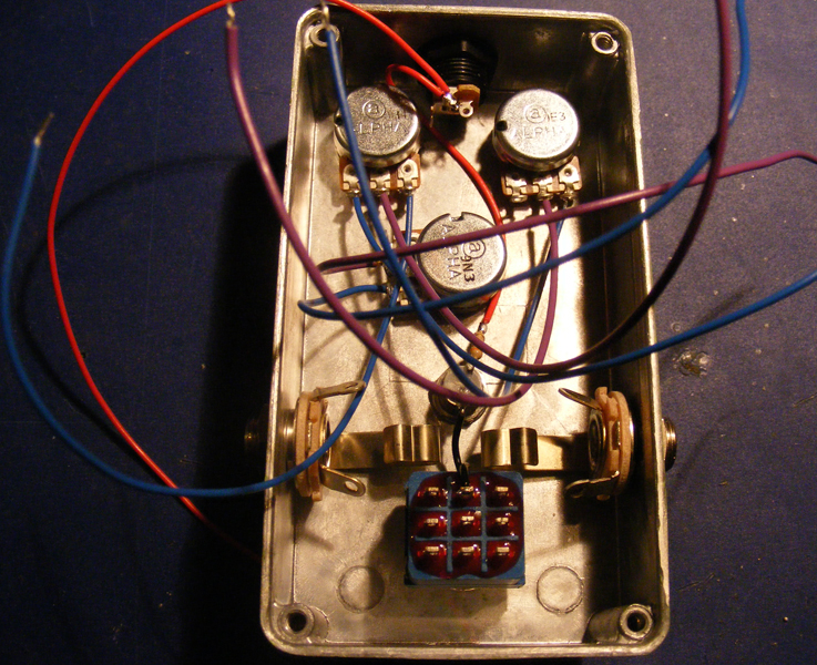
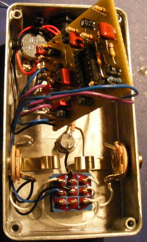
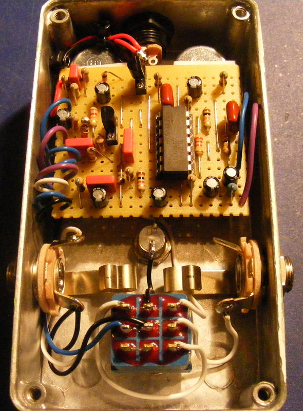
25. I’m about to wire the last pot to the board. In the third picture I’ve attached the last two wires and added the IC and transistors. I always make sure the effect still works (that I’ve wired everything correctly) before I finish up the box.
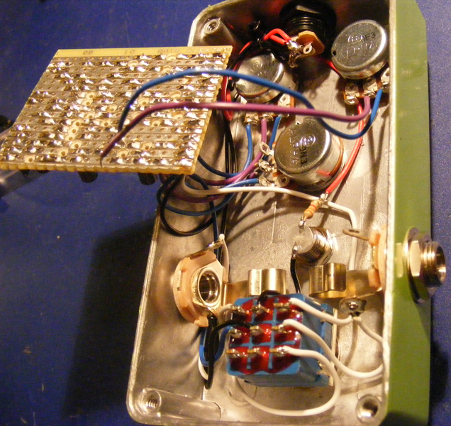
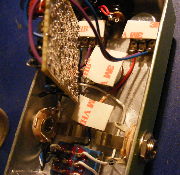
26. I’ve added pads of double-sided foam tape to the backs of the pots (and also the LED because I didn’t want to short against it). The board is carefully pushed down on the tape pads and is now secured. Turns out I didn’t need the pad on the LED after all.
I’m still undecided on how I like to fix the boards inside the enclosures, but I’m reasonably happy with the foam tape so far, and it’s much better than having the board float around inside the enclosure.
Note: If you use this method you need to make sure none of the solder joints/lead ends underneath the board completely pierces the foam tape and shorts against the pot casing. Don’t use too much force when fastening the board, and spend a little extra time doing a proper solder job.
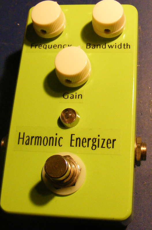
27. The effect is finished!
As mentioned earlier I have yet to learn how to decorate my enclosures properly. For now I’ve stuck on some transparent “Dymo” labels, and finally some cream colored knobs. Not the most pleasing sight, but it sounds nice!
That’s it for my crude step by step guide. Hopefully you’ll have your first working effect ready soon.
Constructive criticism and suggestions are welcome.

Is it possible to add either a ‘Q’ knob or switch to narrow the parametric function?
This was exactly what I needed. Starting my first pedal soon and your tips will likely be invaluable.
Hi Bruno,
Perfectly valid questions. I think I’ve explained the pot lug numbering in the “FAQ” section. Not as sure about the bypass/effect labelling, but check out the “wiring” section, specifically the diagram for buffered effects.
Hi, i’m quite new here and i’m having trouble understanding the pots. I mean, according to the layout… frequency 1,2,3 from which part of the pot do they come exactly? And how can i know that for future proyects? The same for bandwith and gain, sorry if it’s silly. Also what is bypass output and effect output? Do they come from a pot? Or they go from the veroboard to the jacks or the t-bypass button later?
I made a pedal with just one pot recently, so sorry again if it’s silly, but great website anyway!
Sure you can ask 🙂 I actually use version 1. I don’t like the components in the later versions. This does have a number of other drawbacks, though.
Hi Harald, is it OK for me to ask where can I find a complete library like the one you use for DIYLC? I downloaded 3.28v today and the resistors ar huge!
Jacob, it mostly comes down to experience with similar sized builds, and lots of measurements.
I’ve been wondering how you know what size veroboard will fit in what size enclosure…do you know roughly what dimension of veroboard fits into a 1590BB, 1590B, 125B, etc.?
Hi Martin. Look at the “parts sourcing” links on the right-hand side; Banzai, Musikding, PedalParts and Smallbear all carry these boxes.
Sorry for my question, where you buy the metal case for the pedal, sorry for my english i’m a spanish native speaker from Argentina, thanks to the great site
Matt, I have to congratulate you on a great choice of hobby!
I have vero layouts here for the Cranked AC and the Torn’s Peaker, but I would recommend not to start off with the Cranked AC (requires selecting JFETs, which can be a bit awkward as a beginner project). Other than that I would maybe recommend a boost effect for it’s simplicity and low parts count; maybe the Xotic EP-Booster, Brian May Treble Booster or the AMZ Mosfet Boost.
Whatever you choose it’s great to have you on board, and feel free to ask questions (the two forums you find linked on the right-hand side are also great resources for questions).
Hi, I am thinking about building my first DIY pedal, and this site seems very helpful. I was just wondering what a good pedal would be to start out with. I haven’t built electronics before, but I would really like to build something that I will actually use. I was thinking about the Peachfuzz, Cranked AC, MFZ-1, or Torn’s Peaker (in order of preference). What do you think? Are any of these doable for a beginner or should I try something even easier? Thanks!
Hi Reni. First I’ll confirm that I do indeed use DIY layout creator. As for the schematic to vero process that’s really hard. I don’t really have a set of rules that I follow, but rather I treat each schematic differently and try to get an overview of approx. how I think it’s going to fit based on what complex pieces (IC’s, optocouplers, etc.) I’ve got and where there’s “end points” in the form of potentiometers or inputs/outputs. Then I usually go through a revision or two where I move components around trying to find a more efficient layout. It’s hard to describe, really.
But just get started and don’t worry too much about getting it compact in the start. You’ll get the hang of it 🙂
Thanks for all the great info on this website!
Could you also do a step by step of how to convert a schematic to a verolayout, because I would love to contribute to the DIY community.
I know how to do the conversion, but how do you do this efficiently, to keep it compact?
In other words, what are the basic rules when transfering a schematic into a verolayout?
I guess you use DIYlayoutcreator for you layouts?
Regards,
Reni
Hi Vincenzo. Very happy I can be of some help to a few people. That makes it worth it 🙂
For the LED resistor you can use anything between 1k and 10k-ish (or higher, but won’t have much effect). Usually you’ll find that somewhere in between, like 4k7, is fine, but depending on the model, make and color of your LED you may want to adjust this a bit. A smaller value resistor will give you a brighter LED and vice versa.
“Vero board” and “strip board” is two names for the same thing (I’m not sure what a “proto board” is). You’ll want a single-sided board with conductive traces running down the length, either copper or tin/silver is fine (copper is usually cheaper, but oxydize). I just checked musikding and they seem to have it: http://www.musikding.de/Circuit-boards/Circuit-board-material/stripboard-100x100mm::386.html. The “protoboards” they have there is not what you want (notice they have individual pads and not entire strips).
Or you can look for “veroboard” on ebay which is how I usually do it.
Hello Harald, I’ve been wandering around your website for a few weeks, trying to motivate myself for my first buil. Thanks a lot for sharing all this information with all of us, it’s soooooo much helpful, I don’t even know if you realize it! Hahaha! However, I still have a few questions to ask (beginners are always nervous about getting started!):
First of all, what resistor value do you usually put on the anode of the LED? I tried to figure it out by looking very close to the pictures but it wasn’t very clear…
Also, is there an actual difference between vero board, stripboard, proto board… I cannot find a piece of vero board on musikding so I was wondering if something else would do the trick…
That’s pretty much it, thank you for all!
Vincenzo
Hehe, thanks 🙂
That tool is called a hole punch
Just discovered your website and wanted to leave you a big thank for your work! This is a wonderful page with great detail and you convinced me to try out my next project with vero!
Will hit the doante-button soon!
Very useful tutorial, the masking tape tip is great!
Harald, thanks a lot for taking the time to do this page; it’s always helpful to see other peoples’ take on these things. Your website is great! Matt