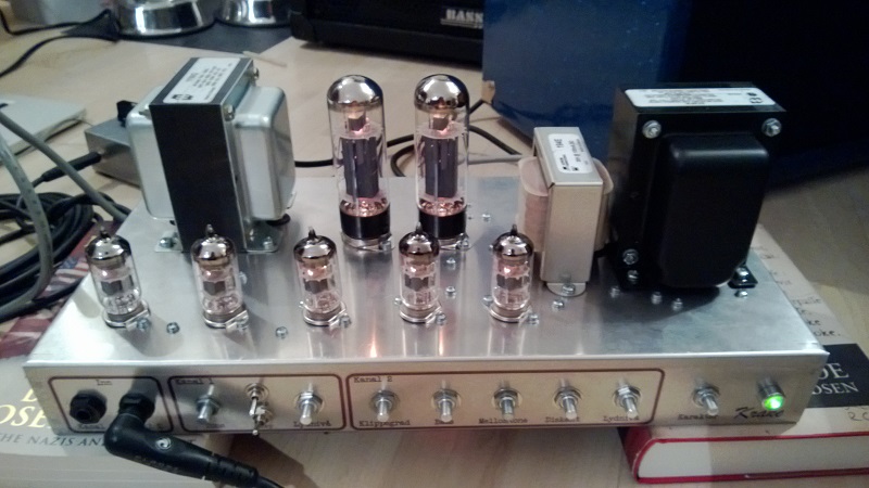
I finally got around to finishing my second amp build, and as I promised here are the details.
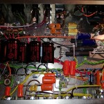
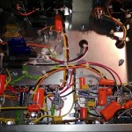
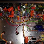
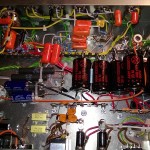
I’m reasonably happy how the internals ended up given that it was all laid out more or less as I went, though I am a perfectionist at heart and this really is far from good enough. Gives me a lot of room for improvements for my next amp, though 🙂
So this all began several years ago when a colleague lent me a Bad Cat Xtreme-tone preamp effect (the one with tubes inside) which I liked a lot. I got my feet wet converting the same preamp circuit to a JFET variant some time after that with the thought of eventually building a full amplifier for myself. To make a long and boring story shorter and less boring I started reading books on the subject, and ended up adding to and modifying the original idea to what you see above.
I’d like to bring your attention to a book that, more than any other, helped me understand a lot of this stuff. “Designing Tube Preamps for Guitar and Bass” by Merlin Blencowe is a surprisingly well written and downright enjoyable book made to help novices like myself getting into this great hobby/addiction (I can also recommend his book on power supplies). I found a lot of the changes and modifications here.
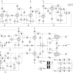
So the basis for the amp is the Hot Cat 30, which again is , I believe, based on a Matchless, which again is based on a Vox AC30. So it has the AC30 power section lacking the typical negative feedback that many other amps have.
I replaced the clean channel with a gain stage borrowed from the Dr. Z Carmen Ghia (a favorite of my friend). Then following this I added a standard BMP tone control with two added switches giving the option of a mid- scoop or boost (or a frequency shift towards bass when both are engaged) that I arrived at by experimenting with Duncan’s Tone Stack Calculator.
For the gain channel I replaced the tone stack with a Marshall one (bass, mid, treble), and followed it by an active parallel/serial FX-loop I got from Merlin’s book. I also got rid of the “edge” control and consolidated the two gain controls into one dual pot. And lastly I replaced the odd first gain stage with a more standard cathode biased one.
The schematic lacks a proper symbol for the output transformer and the following wiring, as well as the input power socket wiring, the heater wiring, the indicator LED + resistor, and the humdinger trimpot. There are also small tweaks to the power supply section as well as a “tube rectifier emulation” switch, all of which was borrowed from Merlin’s book (as far as I remember).
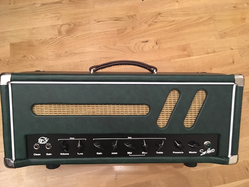
So to sum up, it’s a two-channel clean/high gain amp with an FX-loop, running 5x 12AX7/ECC83 and a push-pull power section with 2x EL34. It’s very loud and very cool, though being a perfectionist there are things I would like to improve/change.
Initial thoughts/lessons learned:
- It’s too loud for home use (I knew this though). Maybe an attenuator will help. Some kind of power scaling would have been nice.
- The FX-loop, though fully functional, could probably be scaled down a bit/made simpler.
- I didn’t get much out of the “tube rectifier emulation” so will probably just stick with plain silicon rectifiers next time.
- The point-to-point-layout-as-I-go ended up looking less tidy than I would have liked. Maybe this amp was a bit too much for such a small enclosure (8″ x 16″). Bigger enclosure or less components next time maybe.
If there’s requests for it I’ll add parts list and voltages. I also welcome suggestions, advice and criticism on anything from schematic and design to building and what not.
I’ll add more pictures when the amp is fully dressed up in tolex etc.
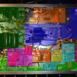
Update (01.05.2013): Here’s a rough overview of the various sections within the amp.
Hi dabes,
I ended up not liking it that much as it had a few minor issues, and it was a mess putting together (those two things might be related!). I used the Hammond 372FX which seemed to hold up fine, but I’ll probably reuse it for a new project down the line.
Congratulations, it looks very well. Do it sound as expected? bad cat Hot cat sound?
What’s the efficiency of the master volume?
You use hammond tranny, it’s good enought (big) for this amp, what’s the reference for the power tranny
thanks
Thanks 🙂 Will try to get sound samples.
Hello back archaos!!! Nice to see you on other sites too as we share a passion for geetar music AND pedals too! 🙂
Harald – that is great to hear – or rather to “not hear” of any problems or issues with the amp! MUCHO KUDOS and congratulations goes out to you. Nothing like having such a personal challenge met and to get to plug into every day. I like to think of it as functional art with the care, attention, detail, dilligence, etc. that it takes. Definitely would like to hear sound samples when you can! _\nnn/ \nnn/_
Thanks archaos,
I’ve read Blencowe and Kuehnel, but haven’t heard of the O’Connor book before. I’ll have a look at that.
Thanks Glenn,
It does play beautifully 🙂 And yes, now my wife gets to yell at me.
Will seriously try to at least get a sound sample up, but I’m too shy so I’ll enlist the help of my friend how actually does know how to play guitar. Stay tuned, but don’t hold your breath please 😉
I very much appreciate the feedback, jojokeo! I guess I forgot to mention it when I posted, but it sounds absolutely great from a technical stand point (i.e. no excessive hum, no parasitic oscillation, no motor boating etc.). It plays as it should from 1 to 10. That being said I did not think about the 10W resistors tied together with the electrolytics off the EL34 cathodes so I will definitely write that down for future builds. And I will try to plan the general layout a bit more as well.
But again, thanks for the feedback 🙂
Nice build Harald !
+1 from what says jojokeo (BTW, cheers from el34world forum jojo)
Have you ever heard from Merlin Blencowe, Kevin O’Connor or R. Kuehnel books, Harald ?
Harald: I think, it looks great. I cant see how neat point to point wiring can really be anyways.
But the bottom line is, how does it sound? any unwanted noises?
When i first built my lightning amp, it looks very messy, but i have no noise issues,and it sounds beautiful to my ears…IMHO who cares what the insides looks like. it wont be on display anywhere.
Like you my fist build was ambitious, (well not as ambitious as yours) but if you dont try you dont succeed!
Now you’re wife will be yelling at you to “turn that damn thing down” which makes it all worth while:)
(if your married)
Good job Bro, maybe you can youtube it.
continued: The penalty for not adhering to these things is induced humm, parasitic oscillations, & more. Trying to pinpoint these problems (if noticed) in an amp built using terminal strips is very difficult and you don’t have many or any options to address this with the layout like this. Grounding is VERY important on a high gain-high power build like this also. It’s difficult to be able to see what’s going on there. Allthough wire ties look neat and tidy, they aren’t really appropriate inside of an amp like this except in certain areas where care & understanding is helpful. Lastly, you have power resistors w/ capacitors ziptied or mounted very close, heat to capacitors is not good which could lead to premature breakdown, wear, and causing to go out of tolerance easily. What’s said isn’t “gospel” and many have successes despite what is mentioned but in many cases these things help prevent a lot of frustration after so much money, care, and effort has been made. Much success to you and as always thank you for your site!
Harald, that’s a very ambitous project for only your second amp build. It looks nice and tidy but there’s a lot of differences between pedal technique vs high gain amp techniques in a lot of ways. You want to keep those heater wires away from all the components, away from the front where all the pots are, away from all those grid & plate wires, etc. When these wires do cross, try to make them do so at right angles. Your plate/voltage wires should be kept away from the high impedance low level signal wires keeping the grid wires as short as possible. You want to try to keep as many wires & components from crossing over each other as possible and the entire flow of the circuit (& gain stages) should be ran from input toward power amp section. Filter capacitors should be as near as possible to their related stages w/ components’ ground terminating as close as possible to respective filter caps. There’s much more – (I’m only trying to help).
jojokeo
Harald you great man!!