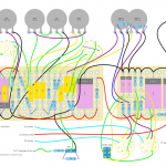
Update (18.05.2014): I’ve made a few changes, mainly removing the FX-loop, and also put together a basic layout since I’ve had several requests for that as well. But to keep in mind this isn’t a simple color by numbers project; you need to know how to wire all of this properly, and you also have to keep safety in mind working with high voltages!
I want to share my third amp build with you today. I wasn’t too happy with the previous one, so this one was going to be better.
The objective this time was a single channel amp that’s mostly clean. I also wanted to use this as a base for future builds by adding an FX-loop, and a volume control after the loop. The idea here is to use the power section for testing other preamps by using the FX return as input, and having the volume control work on this signal.
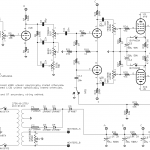
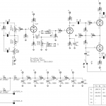
F or the first stages of the preamp I chose a slightly modified DC30 clean channel scaled to work with my HT voltage. I tried a lot of different tone stacks, but fell for an FMV stack I found in a TopHat schematic. This continues into a “practical serial FX-loop” I borrowed from Merlin’s latest book (preamps 2nd ed.), and then a typical long tail PI. The power section is something I put together from a lot of different sources, including Kuehnel’s power amp book, several datasheets and plenty of old schematics, with a dose of calculations and plotting of curves mixed in.
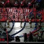
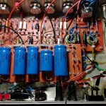
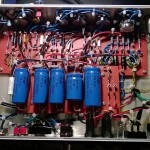
Last build was cramped so I wanted to make this amp less complicated with less components etc… and then I added a bunch of stuff, and before you know it there was very little room left, again. Didn’t help that I went with a smaller chassis either. I’m a slow learner 😉
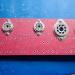
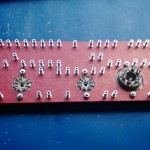
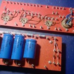
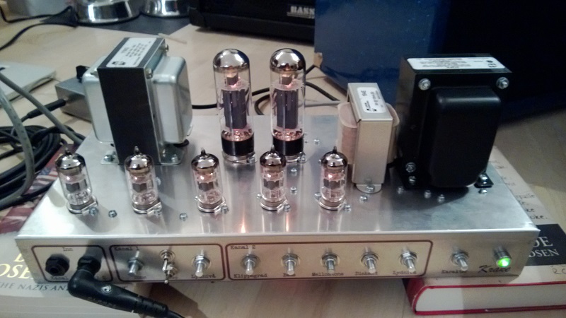
So, with the turret boards and all, the only way I felt I could fit it all in a reasonable fashion was to add the tube sockets to the board and rest it on 5mm nylon stand-offs, moving the large power filter caps to a separate board. Clearly things can still be improved.
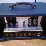
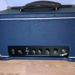
But it works beautifully. Running from clean to some overdrive at max gain (also depending on bypass caps and negative feedback in the power section). That is until I discovered I had the bypass caps the wrong way on the 6V6s. No damage done (other than the caps), but I’ll have to replace those.
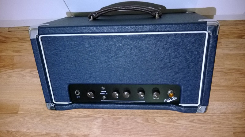
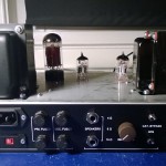
Still missing is a front panel covered in grill cloth. Still waiting for the cloth to arrive from overseas. More pictures to come.
 Update (13.12.2013): I did some minor tweaks to the circuit and accordingly created an updated schematic. It was a little on the bright side (very bright actually) so I increased the coupling capacitor between the first and second gain stage to let more of the lower frequencies through. I did also try doubling the coupling capacitors between the PI and the volume pot, but this had no perceivable effect on the sound so I left the 22nF ones alone.
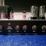
I also finished the cabinet. I didn’t like how the grill cloth came out so I redid the front panel in tolex instead.
Update (02.01.2014): Some more tweaks. The PI has been rebiased for more headroom and the FX-loop has less makeup gain (but also less p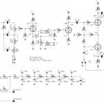 re-attenuation). Several stages have been rebiased, and the second stage is no longer bypassed.
I think it’s an improvement.
Hi Harold,
Any chance I can get a parts list and higher resolution layout? I’m interested in building my first tube amp and found this one at 15 watts.
Whenever or if you have the time, that would be great, thank you!
Thanks for excellent feedback and advice, jojokeo 🙂 I’ll tell you my reason of thinking. Keep in mind I have very little practical experience with amps so I probably got at least some of this wrong.
– First off V1A and V1B, this is pretty much straight off the Matchless DC30 clean channel schematic, only with a single triode instead of a parallel gain stage first, and the cathode resistors modified to get the same bias with my slightly lower HT/B+. You might have a point about the large bypass caps here, I agree. It is perhaps a bit heavy in the lower frequencies. Maybe put these on a fat switch? Hmm… 🙂
– Second, the FX-loop. I know I don’t really need this for a clean amp, but I plan on also using this for trying out higher gain preamps without having to do a complete power amp; the idea would be to run other preamps into the FX return, and this is also why wanted a post-FX-loop volume control.
R9 and R10 was intended this way as per Merlin’s suggestion where I borrowed the whole FX-loop circuit. The idea here is to counteract the makeup gain in V2B when not using the loop. V2B gives approx. 50x gain and R9/R10 is somewhere around x1/50 gain. Without the V2A pre-attenuation this amp is a lot more aggressive with plenty of crunch.
– I can’t remember my thought process when it comes to the PI, so I’ll have to do a little more reading here. Will definitely look at your suggestion.
– Grid stoppers on the power tubes; I did some calculations on the low-pass roll-off frequencies according to formulas from Kuehnel, and found that I could go more than 100k and still be well outside the 20kHz range. But I have very little practical experience with this, so I won’t discount it. Haven’t played this on 10 yet (waiting for that moment when both neighbors and family is out at the same time), but from what I can hear at lower volumes I’m not personally missing any treble.
Hi Harold! Another amp I see what you’ve been busy with 😉 A few suggestions if I may? V1A & V1B are fully bypassed and will provide a bit too much bass & low mids which causes the preamp to distort too soon, giving you not so much clean headroom, and muddiness overall. Lower these to between 1uF & 2.2uF. You have R9 & R10 reversed, 1M as grid return and 22K as grid stopper. Having two triode stages for a send/return loop isn’t really necessary especially for a “clean” amp and again check that bypass cap and it’s value if you actually really feel it’s needed? These will also hinder clean headroom. R18 & 21 limit your drive of the pi for the 6V6s, may suggest using 470/10k respectively again for a cleaner amp w/ more punch driving the output tubes. Lastly, the 47k grid stoppers going into the power tubes will decrease treble response and clarity. I’d suggest going w/ between the standard values of between 1.5K and 5.6K for starters…Hope these things help in dialing in what you’re looking for?