Frequently asked questions
Step by step – A bit outdated, but might still be of help to some of you who are just getting into this hobby.
How do you number switch and pot lugs?
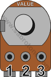


Notice the orientation of the 3PDT. If you have a single- or double pole switch (rather than a triple pole one as in the illustration) disregard “4, 5, 6, 7, 8, 9” and “7, 8, 9” respectively.
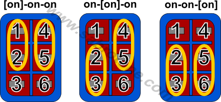
How can I wire a DPDT on-on-on switch as a SP3T instead?
First of all you don’t want the kind of DPDT you often find on guitars, but rather one that throws connections like this:
Assuming you have a switch like this, connect lugs #3 and #5 with a piece of wire. You can now use lug #2 as your center lug, lug #1 as your lug #1, lug #4 as your lug #2, and lug #6 as your lug #3.
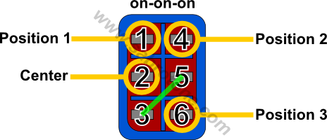
You now have a 3-position toggle switch you can use instead of one of those big rotary switches.
How do I go about biasing JFET circuits?
Lots of effects, particularly preamp emulators and overdrive/distortion, use JFETs (J201 and 2N5457 usually) to achieve gain, and most of these require a specific bias voltage for each JFET to work optimally. There’s two ways to go about it, both requires the circuit powered up and running (take care to power down the circuit before removing or inserting the JFETs):
1. You use whatever JFETs you have at hand and adjust their drain voltages using trim pots. This is common on a lot of the preamp emulators. Measure the voltage on each JFET’s drain pin and adjust the associated trim pot until it reads approx. +4.5V to +5V. Alternately you can use an audio probe and “listen” to the drain pin of each JFET and adjust the trim pot to where it sounds best. Start at the first stage and follow the audio path (see the debugging section for more on the audio probe).
2. Use fixed drain resistors to +V and find appropriate JFETs for each gain stage. This is a more common approach on some of the name pedals out there. You don’t have the luxury of an adjustable trim pot, but are stuck with a fixed resistor. The idea here is the same, you want each JFET gain stage to read approx. +4.5-5V at the drain pin. To achieve this you will have to go through a bunch of JFETs and try each until you find ones that give the proper voltage reading at each gain stage.
How do you add graphical designs to your effects?
See this excellent guide posted by frequencycentral over at FSB.
Where can I find this or that part?
On the right-hand side you’ll find a list of all the websites I personally have good experience sourcing parts from. Some of them are in Europe and some are in the US, and none of them are in Norway (so don’t complain 😉 )
My effect is squealing/whining/oscillating. How can I address this?
This usually occurs because the circuit amplifies the input signal, often several times in cascaded stages, and some of the already amplified signal finds its way back into an earlier stage of the circuit, thereby being re-amplified again and again in a positive feedback loop. This often occurs with high-gain distortion effects etc., but can be a problem with other types of effects you wouldn’t typically call “high gain”, like EQs and compressors.
Anyway, here’s a few suggestions to keep this from happening.
- Keep the input and output wiring separate as much as possible. Both the wiring between the stomp switch and the jacks, and the wring from the stomp switch to the circuit.
- Keep wire lengths to a minimum. Long wires pick up more noise than short ones.
- If wires have to cross they should ideally do so at 90 degree angles.
- Don’t let wires from different parts of the circuit run parallel (wiring from the board to the same pot have to do this to a certain extent). The exception here would be ground wiring, see next point.
- Consider using shielded wire for the most sensitive signals (input and output). Remember to only ground one side of the shield so as not to create unnecessary ground loops. Ground wiring can second as shield when twisted around a sensitive signal wire, which is the exception to the no-parallel rule above.
Your layout says it’s verified, but I’m sure [insert component] is wrong.
There’s two parts to this answer. First of all, yes you might be correct. I call a circuit “verified” when it works in an electrical sense and produces the generally expected sound (i.e. a tremolo circuit modulates the signal amplitude and sounds like what you’d expect from a tremolo). I build and verify many of my layouts myself, but I also rely on you, my fellow DIY’ers, to report your success (or failure) stories, and I trust you when you tell me it works.
Second, a lot of circuits have several revisions where one or more parts differ. I base most of my layouts on schematics written/traced by others and the layout is no better than the accuracy of the schematics. Also, sound is very subjective, and your circuit might not sound anything like some youtube demo that’s out there. That’s not to say there’s anything wrong with the circuit, but there are so many other factors that come into play here (guitar, pickups, strings, amp, amp settings, other effects, recording quality, and even the quality of guitar play).
If you think a layout is wrong do let me know, I do make mistakes quite often. I just wanted you to keep the above points in mind 🙂
Hi Harald. Could you explain how to wire a SP3T rotary switch as DPDT on-on-on? The exact opposite of what is shown in photos. I want to do a series/parallel/coil split with my humbucker but can’t figure out how it’s done with a rotary switch. It can be done with DPDT on-on-on.
Matt, if you’re referring to the DPDT on-on-on then most likely (as long as it really is an SP3T you need), though I know nothing about motorbikes 😉
Totally guitar related….im looking to use a DPDT as a SP3T like the example at the top of the page – to switch motorbike headlights from running-light to dip to high-beam…would that switch setup achieve this?
Turning on the lighting is via the ignition key, so when the lights are actually on, the 3 position switch just selects which one is on
cheers,
Ah, I see. Yes, you’re right, it’s a different use in this case. When you connect the wiper (lug #2) to either side lug you create a variable resistor. Hope you had a great holiday 🙂
Thanks Harald.
By “input” and “output” I refer to lugs 3 and 2 of a pot (1 being the ground lug).
I think I am looking at this from a “guitarmaker” point of view: in a guitar you always solder lug number 1 to the chassis of the pot (= ground), so connecting lugs 2 and 3 together doesn’t make sense. But I see that pots used in pedals/effects assign lug 1 a different role –namely, that in this case the signal enters the pot through 3+2 (so 2, in practice) and exits through 1.
Happy holidays season!
Leo,
Yes, “Frequency 2, 3” means that you should connect both lugs #2 and #3 of the frequency pot to this particular point, easiest implemented by running a wire from one of the lugs and just connecting the other lug with a small wire or resistor leg. And yes, that means those two lugs will be shorted together.
I’m not sure what you mean by input and output in this context.
Harald, compliments for this amazing website.
One question: in some circuit diagrams (your step-by-step guide, for example) it says “Frequency 2,3”, Which I interpret of connecting together lugs 2 and 3 of the Frequency pot. Is that correct, having the input and the output connected to the same soldering point? Wouldn’t it be a shortcircuit?
Kind regards!
Good question, Alex.
Everything on this site is given for free with the intent of enabling people to build stuff for themselves and friends, though I can’t see the issue of someone wanting to sell a handful of pedals to help fuel their hobby. Commercial volumes with the sole intent on making money is a different matter, though, and I don’t approve straight cloning on this level.
I’m thinking that if one wants to build and sell it shouldn’t be a straight clone, but rather take the information available and put together something at least slightly different.
I could go on an on, but that’s my take on it. Handful of units for family and friends is fine.
Is it ethical to sell copies of the pedals? On one hand, I know I can make these and sell them. On the other hand, I don’t really want to feel like the pedal equivalent of the pirated DVD guy on the street.
Hi Harald.
YEP. Building circuits. Good to hear from you. Hope you’re well.
I’m building the Aqua Puss and need to know if a 78L09 will work in place of a 78L08? I know an 05 would not push enuf V’s but can you go higher with the regulator?
dale
Hi Dale. Doing well, though busy these days. Hope you’re doing well too (sounds like you’re building circuits which can ony be good 😉 ).
I’m going to guess the MAX1044SCPA will do just fine without having looked at the datasheet.
Hi Harald.
Hope you are doing ok.
I’m building the 9>18 volt doubler and was wondering if the max1044-SCPA is ok to use. I know it is specialized on overdrive circuits. Will it work on the little board?
dale
Not really. And that’s part of what makes these builds difficult.
Hi.
I asked this b4 but can’t find the pedal I asked under…dope!!!
Is there a general rule for LED and LDR values when putting an opto-thingy together? I don’t seem to see values listed when putting this type of part together.
dale
Hi! My name’s Karen, and I’d like to interview the admins of sabrotone.com for the Featured Engineer column at EEWeb.com. You can view a recent interview from the column here: http://www.eeweb.com/spotlight/interview-with-ian-lesnet
How can I contact you?
Karen Kohtz
karen@eeweb.com
Jyka, you can reach me at: https://sabro.no/sabrotone/?attachment_id=2284
Hi harald you job is great, just begin an SS2 =)
You know where I can email you ?
Thx
The trim pots function exactly like any fixed value resistor with the benefit of you specifying what value you want it to be. Maybe you’re thinking about adjusting the trim pot for center bias (approx. +4.5-5V) versus adjusting it closer to one of the rails (maybe something like +3V or +7V)? The first option will give you more of a symmetrical clipping and the most headroom and amplitude, while the later options will be more asymmetrical. There will be a difference in how they sound, certainly.
I’ve heard that when you use trimpots for drain voltages you end up with good voltages but alter the EQ of the effect in a way, so it doesn’t sound like an exact clone. Is this true?