After having finished the Dominator someone (I can’t remember who) pointed me to the W****** Wriple Treck, and I’ve now done a vero layout for this based on a schematic/trace by Eisy over at freestompboxes. The layout also includes the boost section.
As usual this has yet to be verified.
Update (03.09.2011): Verified this one myself. Sounds great!
Update (20.09.2011): It’s a really cool sounding circuit and a strong competitor to the Openhaus and the Dominator. I think I like this one the most, but then again that might just be the newness factor.
Update (20.10.2011): Fixed dead picture links.
Update (11.11.2011): Voltage readings from my build:
Battery at 9.35V, all pots fully clock wise, effect on, boost off, no input signal. Battery after reading at 9.18V.
| IC1 | IC2 | IC3 | |
|---|---|---|---|
| 1 | +4.34V | +4.22V | +4.31V |
| 2 | +4.35V | +4.28V | +4.31V |
| 3 | +4.15V | +4.27V | +4.12V |
| 4 | +0.1mV | +0.1mV | +0.3mV |
| 5 | +4.15V | +4.27V | +4.25V |
| 6 | +4.34V | +4.27V | +4.25V |
| 7 | +4.34V | +4.37V | +4.18V |
| 8 | +8.53V | +8.51V | +8.47V |
| Q1 | Q1 (boost on) | |
|---|---|---|
| E | +153mV | +90mV |
| B | +722mV | +276mV |
| C | +1.23V | +4.3V |
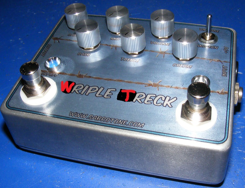
Update (09.10.2012): I was asked to refrain from using the company and product names, so layout has been updated accordingly. The picture of my completed build with the product name on it was also a big no-no so I’ve fixed that one too.
Update (21.10.2012): There has been requests for a version without the boost. I didn’t want to spend too much time on this, but I figured I’d remove the relevant components from the first layout at least.


hi , Harold….can I power it from 18 volts?
Hi Pete,
Anywhere you’ve got an electrolytic you can probably use a regular capacitor instead, as long as you can find the correct value and voltage rating. The reason electrolytic are used is due to cost and physical size when you get up in the uF range.
Do note that the same is not true with regards to replacing regular capacitors with electrolytics, as the electrolytics must be oriented correctly with regards to voltage or they may blow up.
Supposedly, electrolytics sound worse when used on audio signals, but I doubt it would make a noticeable difference in most circuits.
Hey Harald,
Building this one at the moment and noticed something – The C28 capacitor on your layout is electrolytic, but the one on Eisy’s schematic is not. Would it matter if it is or not?
Worked on breadboard, but currently dead on my veroboard – gotta check my soldering.
Hi Jay,
Pins #6 and #7 on IC3 looks like suspects. I would have expected these to stay at approx. the same voltage as the others. I’d start looking in that area first. Maybe a solder bridge of a misplaced component?
Great to hear 🙂 Thanks for the build report.
I have no sound when I turn the effect on.
I wired it like this https://sabro.no/sabrotone/?attachment_id=3472.
My voltage are:
IC1 IC2 IC3
1 4.70 1 4.66 1 4.68
2 4.70 2 4.69 2 4.68
3 3.19 3 4.67 3 3.20
4 0 4 0 4 0
5 3.19 5 4.66 5 4.64
6 4.71 6 4.68 6 2.82
7 4.71 7 4.70 7 8.69
8 9.42 8 9.38 8 9.36
Thanks, harald! This was my first real project and I got it to work with only a few hiccups. First had no sound at all and went back in and cleaned up some of the soldering and I think one of the ICs was not mating well in the dip socket (I must have gotten cheap dip sockets).
Now it sounds great. I used the no boost version, but I may go back and add it in. I personally like a very heavy sound.
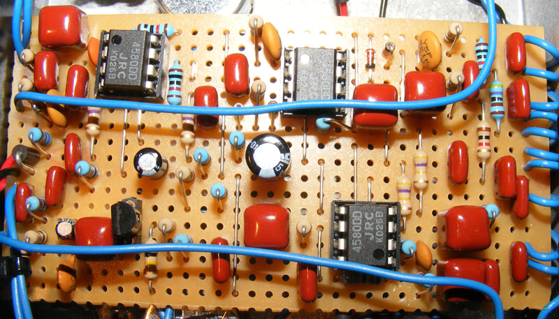
BTW, I saw some people had issues with getting parts, just wanted to say I found all the parts on Mouser. They have the JRC4580DD chips (called NJM4580DD now), they had nice small 1uF 16V caps.
For the enclosure, I used an old cookie tin, maybe I’ll try to post a picture later. All told, I spent about $30 US and 20-30 hours assembling and troubleshooting. On to the next one!
Thanks Alex,
I’ll add that some transistors, depending on manufacturer etc., varies when it comes to pinout, so it’s always a good idea to check the datasheet of the specific transistor you’re using and line it up according to the text on the layout (and not the layout symbol).
“E” stands for Emitter, “B” stands for Base and “C” stands for Collector. Those are the legs for this kind of transistors. You have to connect the “Emitter” leg on the top.
If you look at the layout, you have to put the flat face of the transistor towards the C28 side. The legs will fit properly as EBC from top to bottom.
Hello, Harald.
I’m doing this great project but I don’t understand what you mean in “Q1from top to bottom E B C”, could you explain to me? (I’m sorry about my english.)
Thanks! I’ll experiment with shorter wires and shielded wire. I fiddled with the wires a bit and that already reduced the noise. I don’t think I can get it to look as clean as yours though. 😉
That’s quite common on high-gain builds. Check out the FAQ section, Bart.
I meant to say: the last 20% of the gain.
Thanks for this layout, Harald! I used the boost in front according to your add-on in front wiring layout. Seems to work nicely. I do get a high oscillation (squeeling) sound on the last 20° or so of the gain knob when I’m not playing. I’m not sure if that could be considered normal? Other than that it seems pretty quiet.
Thanks, Dale 🙂 By the way, feel free to talk about any and all relevant sites. I don’t mind.
Just finished this ..fwipple tweck. What a dynamic sound. EQ is great. I am going to try some different chips out of curiosity. I’ve just recently found your sight and have been building tagboards from the ‘other’ sight. Everything about your sight is better by far. The other sight is great……do the math. Thanks. I am am looking for something like the trip wrck to build next.
Hi Ed,
Looks like you’ve got the switch numbering down. There’s an illustration in the FAQ section, too.
Hi Harald
Building the layout, can you help with th wiring of the vin/ mod switch
Numbering and location of the poles on the switch
Is sw1 the top outside pole and sw2 the center pole
Thanks Ed
That’s what I hear. When I put mine together a long time ago I had to guess, and I placed it after. Still works, just different 😉
Not sure to be honest.
I used NJM4558, but it sound awesome. I’ll try to get a clip up for you harold!
Boost goes first. I’ve read a comment of Brian Wampler about the circuit in a diy forum where he corrected the Triple-Wreck schematics.
Now that I’ve listened to some clips, that’s definitely what the crunch/cream control is, and the boost is most definitely first, it takes the pedal into muff like territory.
Is the boost control on this a sweep of which range to boost?
Hi topan. Haven’t tried with TL072. Mine sounds pretty much identical to the youtube demos for this thing, except I put the boost section after the main effect whereas I’m not sure whether the original perhaps has the boost in front.
sorry harold, my mistake
i think your layout absolutely true
thx 4 this layout, i wil build TW with this layout
can you compare your sound result to the original?
have you try tl072 for your TW?
thx man, great site
Sounds great, Pierre!
Forgot to say that it is recorded at a very low volume on my G5 amp (early in the morning, wife sleeping) just with my iphone on the floor…
This one is a real riff maker. Played it 15 minutes and 4 ideas came to me.
https://soundcloud.com/gen-t314/sets/3wr
Singing harmonics, nice eq. Boost is plugged in front with R28 lowered to 22K to get a right voltage on Q1’s collector.
Many thanks for this monster Harald.
Can’t wait to try it on stage as the pinnacle tomorrow!
😉
Hi topan,
I used the schematic from that thread. The layout you link to seem to be without the boost section, could that be it?
Hi harald thx for this layout..
I found layout from http://www.freestompboxes.org/download/file.php?id=12398&mode=view
i found some different placement part, for example C3.
Are you use a some schema or you trace by yourself
thx a lot and sorry for my bad english 🙂
Great looking build, Dennis!
Now it works perfect 🙂
http://www.jem2kdna.de/blog/diy-triple-recto-in-a-box/
Thx Harald. Found the mistake. Got the wrong transistor, 2N5462 instead of 2N5089. Will change it tomorrow. Again thx for your answer. Btw: I checked the wiring twice 😉
Hi Dennis, sounds like Q1 is not working correctly. Have you checked the pinout on the datasheet of your particular transistor? I suggest a visual inspection of the area and components surrounding Q1 (check out the new debug section for some tips); there might just be a simple mistake there somewhere. Also, have you checked your boost switch wiring? Have a look at the wiring section for some ideas.
Hi Harald, I’ve finished “my” Wriple Treck yesterday and it sounds great. But I’ve got a little problem: When I turn on the Boost section I only hear a big hum. I’m able to change the intensity of hum but the guitar signal is completely off. Any ideas to solve this problem? Thx in advance.
I still think it’s a lead dress issue, but the ICs could be part of it. I bought mine from banzai music (link on right-hand side). The 330n caps should work, but they do change the frequency response of the effect somewhat.
It’s behaving quite odd. with any op amp other than a standard JRC 4558 it howls like a banshee, and sound super muddy and cruddy, i didn’t have 220nf and used 330nf, is that what my issue is? too much bass? I have a patience problem. also, where can I find 4580D?
Mike, this is a very high gain circuit meaning you have to be very careful about lead dress, i.e. there are a few common rules when it comes to wiring these types of effects. For an in-depth understanding I suggest searching the forums for wiring high gain effects, but the gist of it is that you need to keep wires short, keep parallel runs of wire to a minimum (cross at 90 degree angles if possible) and separate input and output wiring as much as possible, even going to the lengths of using shielded wire for these.
Hey, Ive built this and all the knobs work as expected… but it oscillates severely past even a 8th of the gain knob, and hisses quite badly. What am I doing wrong?
Harald – Thanks for the reply, got it figured. A cold solder on one of the IC legs. It is now working. It is very noisy though, but I have not boxed it yet so maybe it will get better when I do.
Very nice sound overall though. I love how it is bassy without being muddy. Sounds very excellent with palm muting. Thanks for the layout!
Hi Keith. I’m thinking pins 1-3 and 5-7 on IC1 and IC2 look off. I would think these should sit closer to the bias voltage (~4.5v). IC3 looks better, but there are some odd readings there too.
Have you done basic debugging and also made sure you’ve got all the trace cuts, jumpers etc, including the ones underneath the ICs?
If you look at the post you’ll find my voltage readings, and your build should roughly match this.
Hi TheCobbenator. I’ll try to throw together a “non-boost” version.
Trying to build this and can’t get it to work. No sound at all. Getting no voltage at volume pot nor at R18, R19, and R20. All voltages in (V)
IC1 – pin #1: 7.93 pin #2: 7.38 pin #3: 7.32 pin #4: 0 pin #5: 7.32 pin #6: 7.91 pin #7: 7.91 pin #8: 8.48
IC2 – identical
IC3 – pin #1: 4.33 pin #2: 4.34 pin #3: 3.08 pin #4: 0 pin #5: 4.27 pin #6: 1.04 pin #7: 7.84 pin #8: 8.47
Hoping maybe someone has an idea. I’ve built lots of PCBs before without much issue. This is the 1st time I am stumped. Is there a schematic that this vero was based on? Maybe that might help me.
Hey Harald! I used to own one of the original wripple trecstortions and wanted to know — how could I go about omitting the boost switch and cream pot altogether? Thanks!
Me too! It sounds great 🙂
love the wriple treck 🙂
Fair enough. I’ll change it.
Sorry to ruin your fun (as we generally love the DIY and MOD community), but the names “Wampler” and “Triple Wreck” (in regard to guitar effect pedals) are trademarked to Wampler Pedals Inc.
Please remove all references to our trademarked product from public view. If you wish to continue using our product as a reference point, you cannot refer to it exactly and you cannot produce a clone called the same thing. The above picture of a completed pedal called a “Triple Wreck” is in direct violation and needs to be removed immediately. If that product has been produced for sale then you need to remove it and not produce any more under that name. Any direct marketing of a product that claims to be the same as ours will also be a violation.
Thank you.
1000uF of filtering and lots of shielded wire did the trick. the pedal is quite silent at gain 3 o’clock. Past that i get a big noise boost but who needs that much gain anyway 😀
Hi Sannu. Mine is actually appreciably quiet at all settings. Try powering it with a battery to find out whether it’s power supply noise, or it might be due to lead dress where you have long wires tangled together etc. (there’s good info on the forums about good wiring practice in high gain pedals). Other than that I’m not sure I know what the problem could be.
Hi Harald,
I was wondering how much noise do you get with your WTW when the gain pot is near maximum? Mine has a lot of buzz when the gain is in the middle and max gain is nearly unusable.
Sannu
Hi P! Great to hear you’re getting your hands dirty, and a very cool (and challenging) first build 🙂
For the vintage/modern switch you only need to make or break contact, so an SPST off-on mini toggle will suffice, but you can just as well use an SPDT on-on, just leave the last lug disconnected.
Use a 3PDT on-on for the stomp switch (push on/push on). Almost everyone use the blue ones you’ll find on most stompbox-centric electronics sites (or buy them in bulk on ebay).
You can probably get away with using a linear 100k pot or maybe a logarithmic one in reverse, but the C100k’s should be easily sourced from e.g. http://www.smallbearelec.com (where you’ll also find the blue 3PDT’s). There’s links to a few other sites as well on the right-hand side that I can vouch for.
Also, specs/type (i.e. momentary, push on/push off, etc.) on the 3PDT switches, and other options for the 100K reverse audio pot (as I’m not able to source that particular spec pot)?
Thanks!
P
Hi Harald, et al…
Awesome site!
I’m fairly new to electronics. I’m building your TW circuit as my first ‘from scratch’ pedal (having modded a few dozen pedals), and I’m unsure as to exactly what type of toggle to order for the Vintage/Modern switch – i.e. on/off, on/off/on, etc. – and what voltage/amperage specs are required for the toggle.
Thanks in advance for pardoning my noob-ness/any assistance!
P
@Ed. yup the wiring layout i did moved the boost circuit in front of the main circuit. i don’t really fancy it and i’d rather prefer the boost wired after the main dist to serve as a volume boost – if only i can lower it though as it is too loud. i might try the modification in fsb to make the cream section more usable
http://www.freestompboxes.org/viewtopic.php?f=7&t=10737&start=240#p198514
Hi Harald
Were you able to come up with an illustration for you off board wiring?
Ryan, did you wiring layout work out to be successful?
Getting ready to do this build, still a little shaky on some of the off board wiring for switching
Thanks Ed
i edited the original wiring using paint. this is how i rewired my build and everything’s ok so far. nothing fancy about this configuration though.
http://farm8.staticflickr.com/7253/7595544944_50c24d5808_b.jpg
Ah, at the time I had no idea on what side of the circuit the boost should go so I just added it at the end. It should be quite straight forward to wire it in so that it’s ahead of the main circuit instead. I’ll see if I can make an illustration for this as well.
I’ve got a basic illustration of wiring an effect with an add-on in the “schematics & drawings” section. That’s how I wired by build.
Hi Harald. It seems that the wiring we follow (based on your site) puts the boost after the main circuit whereas it is the opposite on the original pedal – boost comes first before the main circuit. I guess that explains why I get a huge volume boost instead of a difference in the drive characteristic. I have made some changes to the wiring and test it later. Still not sure if I will just leave the current wiring and try to lower the amount of volume boost.
http://farm8.staticflickr.com/7253/7595544944_50c24d5808_b.jpg
Ive read through all the posts, I’m still a little fuzzy on the wiring of the 2 3pdt switches for effect and boost.
Can any one offer a short narrative or sketch
Thanks
Ed
Thank you Harald, for this layout.
I built mine and finished it yesterday.
The sound is awesome, nothing less, and very quiet.
I could not get the JRC4580, so I used three RC4558P that is so close to JRC4580.
Later I tried to change IC1 to a OPA2604 and the sound was horrible.
I tryed with another OPA2604 and the sound remained horrible.
So, I put back the RC4558P and I am happy with it.
In my pedalboard the Wampler Triple Wreck is side by side with a Dr.Boogie (made by me), a Catalinbread Supercharged OD (original factory) and a 56Inc Tubestation Recto/SLO.
The only pedal that beat Wampler Triple Wreck was the Tubestation Recto/SLO because it uses three 12AX7 tubes, which is a copy of a pre-stage of Mesa Single Rectifier with 2 channels.
Below, if you allow, I post the link with a picture of my building:
http://i223.photobucket.com/albums/dd90/Kroydon/Ramsay003-1.jpg
ok, so i got my NJM4580’s (they are actually JRC4580) and replaced the TL072’s. not much difference or may be I just cant distinguish it. one thing I noticed is that the boost really boosts the signal in terms of loudness. I mean it gets reaally loud! is it normal? anyone noticed the same with their build?
Ah, well going with different opamps you might actually notice a difference. As long as you keep the pinout in mind go with the one you think sound the best 😉
Sorry.. I meant about the difference between TL072 and the 4580. Anyway, I have a bunch of NJM4580’s incoming so I can do a comparison.
The different prefixes refer to the manufacturer of the IC. I’d think most 4580’s will sound similar.
I just finished building this and it’s really good. Mine isn’t as high gain as the original though. I’m using TL072’s since I don’t have any JRC4580. Would it be a lot different if I used NJM4580’s?
Me too! 🙂
Damn, this pedal is a beast! Thanks again Harald! To be honest, I love it more than the Dominator
ok, just used the layout in the schematics & drawings section. You have to be careful thou. I had it one way routed one way and when engaged didn’t work, but with the wiring exactly the same and just taking the input jack off the enclosure and ground…it worked. I connected the wires in a different way and got it working. WOW, great “growl” to it. I’m just playing thru a practice amp and it’s late 2am on a weekday, so I’ll fire it up tomorrow on a real combo. I’m sure it will be even more impressive. Thanks again!
Equinox
Ok, found it – https://sabro.no/sabrotone/wp-content/uploads/2011/11/Layout_circuit_w_addon.gif.
Thanks Harold. I usually wire my stuff based on the “Gaussmarov method” I’ve found it to be the easiest for one pedal. I’ll see if I can adapt it to this one for feeding the distortion into the boost. – http://gaussmarkov.net/wordpress/thoughts/wiring-up-a-1590b/
Thanks again and great site!
Equinox
I put up wiring illustrations in the “schematics & drawings” section. Personally I wired this according to the “main circuit with add-on/boost stage” diagram.
Can someone please post an actual layout of how to wire this?? I can’t seem to figure it out and it’s very confusing the pics are not quite high res. enough to see where the wires are going and the twisting makes it even more difficult! 🙁 Please post a link and thanks in advance. ….other than wiring, everything is drilled and populated and ready to go! 🙁
Equinox
Thanks Harald!
This makes a lot of sense to me!
I’ll post you as soon as possible my comments on some of your layouts! (Scary thing is: I’m a Vox AC30 player!…)
Hi Matt. It just so happens I recently wrote about this in connection to the F. Briggs Hummingbird overdrive (https://sabro.no/sabrotone/?p=2517). Hope this info is of help.
Really nice work!
I’m looking forward to build this one but i have many douts on which kind of caps should i buy!
Fil, Tantalum, Silver Mica etc!
Is there a clear rule for every cap i have to mount?
Thanks
Can’t wait to try this one with my AC30 😛
I’m not sure what would be a good substitute. I’d try google and see if anyone else have asked the same question. Probably have.
what can i use for 2n5089 ? there is no 2n5089 in my country
Finished this one tonight. Worked right off the bat and sounds great. It has a nice range of low gain that I prefer over all the “metal” sounds this box can spit out. Nice EQ. The boost is down right nasty. I’m not sure if I’ll ever use it live, but it does sound pretty much like the TripleWreck demos. Nicely done Harald. Thanks!
Well, the layout should work as it has been verified several times. I’m afraid you have to start debugging. Be systematic, make sure all components are placed at the right location, are of the right value etc. Look for solder bridges. Read the debugging pages over at http://www.geofex.com
oops. sorry. the boost section is the only thing that is working. and i dont know why but i’m getting way higher voltage readings. they aint less that 5.6 v
Hi Harold.
i built one just like this but cant get any sound out of it. it just boosts the sound a bit. bass control is the only knob that is working. boost section is not working at all. the only changes i made were using 2n5088 instead of 2n5089 and 1n4002 instead of 1n4001.
i double checked and even triple checked everything. no issues. can you give me some ideas what can be wrong here?
thanks.
(btw it was me who asked for a triple wreck a in your blog some time ago =) )
Hi harald,
Today ì finished this effect,and woww..its amazing,.the EQ is cool,.i like it
thanks harald
Hi Harald,
thanks for your answer. I did put C24 a the wrong place… All working fine now. It does sound very good. I personally think the boost is not that great, other than that, I am very happy with distortion.T
Thanks for your time and your hard work.
Ben
Can’t tell you what’s wrong, but I’d do a thorough check to make sure you’ve got all components right (right value at the right place). If that doesn’t turn out I’d try to trace the audio signal through the circuit using an audio probe.
HI Harald,
I have built the Triple wreck and I have the same problem than Make/Shift, the output signal of the distortion is extremely low. The boost section works perfectly. I have check my vero layout for an hour and the is no problem, mine is similar to yours. I have check the voltage on each ICs and it is similar to what you gave above. Any idea of what the problem might be? I know that you have made it successfully, along other guys.
Thanks for your time.
Ben.
Hey Harald,
Your site is awesome, i built your para EQ and worked first time. This pedal is giving me alot of trouble.
I can hear the signal being affected by the gain, eq and volume but it is extremely low signal, i have to crank the amp up to maximum to hear the faint signal
Can you help me and future builders out by posting the voltage readings around the IC and the transistors.
Harald. You sir, are an effin’ legend. Cannot thank you enough for all your help & support & for the fab layouts. Keep up the good work dude! Milkit.
I feel another donation coming on! ;0}
Thank you very much for the offer, Milkit. You’ll notice I’ve added the circuit wiring diagrams already, though I appreciate the effort 🙂 And congratulations on finishing your build.
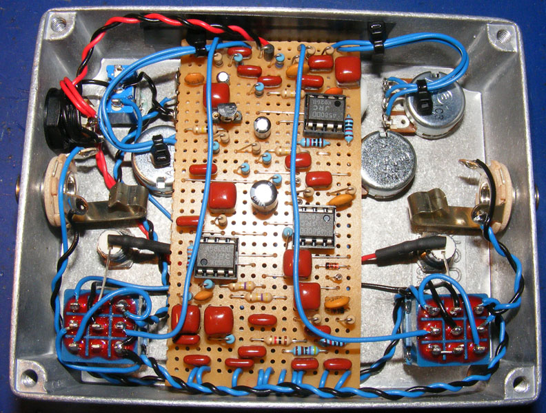
Thanks Harald. Gotcha! With a little bit of patience, a little common sense and a keen eye, I’ve managed to suss it out from your gut shot. THIS IS ONE SWEET ASS PEDAL! Took me a while to build and I’ve had to “shoe horn” it into its enclosure, but man is it COOL! Thanks again Harald for all your top help dude.
I have drawn a diagram of the 3PDT switching layout, but will document it in DIY.L.C. As favour to you for all your help, would you like me to email it to you so you can post it here, or would you rather do your own? I don’t want to step on any toes! Thanks, Milkit
Hi, Harald…
Thank you for your posting…
I made triple wreck by your posting but mildle range nobe not work…
Could you tell me where i have to check….?
That one is close, but probably not what you want. Wired like that you’d have two separate effects that can be turned on and off separately, i.e. you can run just the boost without the main circuit. It’s basically just two stomp boxes merged into one enclosure. You want a slightly different wiring where the boost can be engaged or disengaged only when the main circuit is turned on. I actually drew a schematic for this wiring when I did the Hot Cat emulator circuit. You can find it under “Schematics & drawings”, it’s a tad hard to read/understand though I imagine. I’ll try go get an illustration together soon.
Just out of curiosity, is this one any good? http://www.generalguitargadgets.com/pdf/two_in_one_wiring.pdf?phpMyAdmin=78482479fd7e7fc3768044a841b3e85a
My apologies for badgering you buddy! Milkit
Thanks Harald for all your info dude. I can appreciate you being busy. Look forward to that diagram when you get chance. Milkit
I don’t use water slide decals, I use transparent film sheets for inkjet printers. After cutting the graphics to shape using a scissor I use a transparent spray-on photo glue. After having secured it to the enclosure I follow up with 4-5 rounds of clear coat.
I’ve got a lot to do these days, but I’ll see what I can do. You’re not the first one to ask so I’d like to work out a diagram of sorts. On my todo list.
Sorry, also meant to say, your graphics are sweet, what do you use, is it waterslide decal paper & if so, is it laser or inkjet paper? Thanks, Miklit
Hi Harald, Parts still haven’t arrived yet, but I’m getting everything ready for when they do. Could I be a ultra pain in the backside and ask, how do you wire in the two 3PDT switches? I’ve been searching on the net on how to do it and I have found a few diagrams, but with so much difference of opinion and I’d like to get this one right!! Do you have a diagram you could post on here, or email to me please? Hand drawn would be fine thank you. Kind regards, Milkit
Great! Happy building 🙂
Dude I found the DD’s on the banzai site and an order has been placed. Super thanks again buddy! Milkit!
Found it, sweet thanks Harald, you are indeed a legend!
Thanks for your info & help re: the IC’s too, it’s really appreciated, so much so in fact, I’m gonna donate!
The 4580DD is a standard pinout dual opamp so you can usually use a TL072 in a pinch. It probably won’t sound the same, but you’ll at the very least be able to verify the circuit as working. Incidentally I picked up my 4580DD from Banzai (in my parts sourcing links on the right hand side).
I won’t post the schematic since it’s not mine, but you’ll find it in this thread over at FSB: http://www.freestompboxes.org/viewtopic.php?f=7&t=10737
If for some reason it’s gone let me know and I’ll email it to you.
Hi Harald and all the guys in the forum, this is me being totally lazy, not to mention a little bit lost. But I’m having trouble locating some JRC4580DD chips here in the U.K. (it’s a pretty rubbish source for these kind of parts) I’ve searched for substitutions (& this is where I’m getting lost) would a different chip suffice, say a TL072 perhaps or something similar (I have an abundance of those bad boys!) The only similarity to the 4580DD I can find is the SIL array type on Das Musikding.
http://www.musikding.de/product_info.php/info/p377_JRC-NJM4580L.html
Could I use this one and just re-pin out accordingly? (data sheets make my brain hurt)
And to be uber cheeky, could I possibly get a copy of the schematic from you please? I’d appreciate it greatly dude.
Many thanks,
Milkit!
As far as I know it’ll be back again soon. Unfortunately I didn’t draw the schematic in question and I don’t have posting permission, so I won’t post it here. I can however pass it to you in private.
Hi,
please post the schematic of the triple wreck. It´s gone on freestompbox.
Thanks
Maik
really wanna give it a try? anybody built it before? i’ll try mu luck building it tomorrow. hope it has no issues as always…
i’ll post the results in 30 hours =)
Yes, think I’m going to give this one a try. My expectations are high 🙂
nice work Harald, as always.
After having built the dominator I decided to built that beast too. Though I didn’t use your layout I have to admit I like the Triple Wreck even better … in my ears it’s meaner than the dom, has a cooler EQ-section, is quiet as a grave and that boost haunts the shit out of me. I definitely recommend building this monster!