Vero layout of the ISP decimator noise gate. This one is based on a “true-bypass” version of the schematic foregoing the IC switching, buffered bypass and whatnot. I’ve yet to verify this (as usual) but it looks interesting enough that I’ll give this one a try soon. Let me know if you beat me to it.
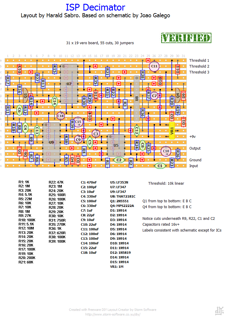
Update (30.12.2011): Just finished building this circuit and it works.
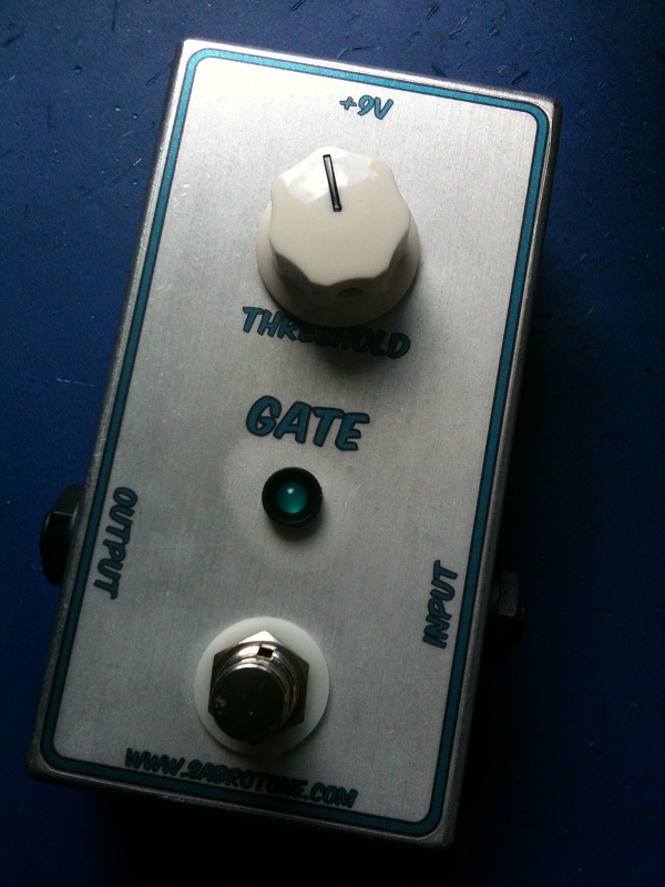
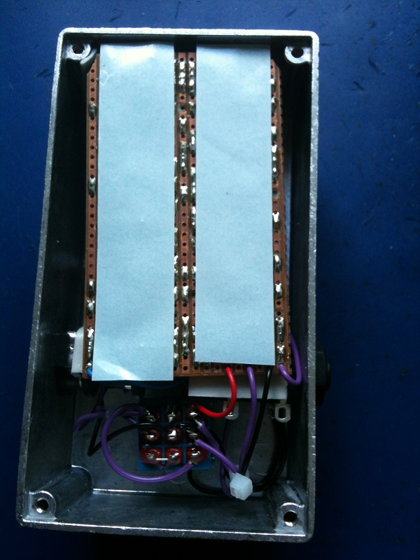
Update (06.08.2012): I really wanted to fit this in a 1590B, but given the size of the vero that wasn’t going to happen any time soon. I went with the next size, the 125B, which was still just barely able to house the board. Placing it component-side down was the only way it would work and that’s why the insides are as disappointing as they are. Love the effect, though!


I believe that is one of the most significant information for me.
And i’m satisfied studying your article.
But wanna observation on few common issues, The website style is perfect, the articles is
in reality nice : D. Good job, cheers
My brother recommended I might like this web site. He was once totally
right. This post actually made my day. You can not believe just
how much time I had spent for this information! Thanks!
I just finished this. It is as per the original, but the buffer is very much needed. Without a buffer at the input, on cleans, you can hear wolf note artefacts in parallel with the original sound, like a doubling of sorts but with distortion . It goes away completely with a buffer.
My build here:
https://hgecontraptions.blogspot.com/2023/05/built-isp-decimator-clone-142nd-pedal.html?m=1
Thank you so much Harald, a friend actually bought this from me when I finished it heh. and I did own the original as well and can say they are almost identical and could not distinguish differences (with the buffer at the input included).
For all who are not getting this to work, 100% you are doing something wrong. What I can tell you is that most of the ICs are not crucial except specifically for the THAT2181C variant , and that Transistor MPSA2222A, these are crucial. I socket usually everything to test stuff, and nothing worked as intended in that transistor spot.
100% working and perfect
Built and is not gating signal. Adjusting trim and getting different results. The closest I get is the noise fades out like it should when when I turn the threshold up. Then noise returns after a brief moment being at its new position. Strong signal both on and off. Anyone encounter this and have a solution? Thanks!
The schematic calls for a 22M resistor (huge), but whether such a large resistor is required or even correct I cannot say. If I were to bet, a 2M2 would probably work fine.
R5 resistor 22m? or 2,2M?
Built with and works well. Gstring works both in FX loop, or up front with drive pedals in gstring loop. I used both a THAT2181C and 2181LB.
The add-on seems fine as is. It replaced C3. Ignore the “U7.1”. You want ti to make connection with U5.1
Let me clarify the labeling looking at both layouts:
-In: Guitar in
-Out: Decimator Out
-Send: Guitar Out
-Return: Decimator In
Vr goes to any vr point on your main board, such as: P1, P7, L15, i18.
same request
i have build it and it works great. Thanks for layout. Can you please share some info how to add a g string addon that is posted here: http://diy-layout.com/75 ?
What to connect where especially vr and r3 and c5/7.1 connection. Please, appreciated your help.
Hi,
i have build it and it works great. Thanks for layout. Can you please share some info how to add a g string addon that is posted here: http://diy-layout.com/75 ?
What to connect where especially vr and r3 and c5/7.1 connection. Please, appreciated your help.
Larry
Not my schematic, so I’m not going to post/host it, but here’s a link to somewhere else on the Internet: http://2.bp.blogspot.com/-l2NRTEh3J54/T-8ppoN5mNI/AAAAAAAABm0/L-RQt6ykI84/s1600/ispscheme.jpg
Schematic ?
I’ll try to get some voltage readings from my build, Daniel.
Tim, where is your threshold set at in relation to adjusting for unity gain? My build seems very hard to find that “sweet” spot; I’m using the 2181C version also. Can you post some DC voltages please?
I built this several months and and it works.
A comment:
the trimpot is supposed to be the “level” control. you’re supposed to adjust it so that the bypass signal and gated signal are at unity gain, however I find that unless the trimpot is essentially maxed, the gate doesn’t work, and this also means that the signal is significantly hotter than the bypass signal.
I used the C version of the THAT chip. not sure why this is happening though.
Otherwise the is outstanding!
Sorry to disappoint, Chris. Not sure how one would effectively go about debugging a gate. Have you checked out the extensive thread over at diystompboxes? Maybe you can get some ideas from reading that.
Harald,
thanks for your reply. I was able to get a C version of the 2181, but that does not change really anything about the circuit’s behaviour, sadly 🙁
Any hints on how to debug a noise gate ? How does the circuit work in general?
I built myself the audio probe cable and its quite nice to go into the circuit and listen to the signal at that point but i am not sure at all, how the gating circuit really works.
Cheers
Chris
Sorry it’s not working, Chris.
Don’t quote me on it, but I do seem to recall a discussion on this effect where someone found that the “B” version of the IC didn’t work but the “C” version did. I have only tried the “C” version (bought from mouser) which worked great so I can’t confirm this.
Sami, check out the debug section. I’d try using an audio probe to narrow the scope of the problem.
Hi Harald,
I fininshed it just an hour ago and can’t get it to work. I traced all the soldering points and it looks quite good. Here’ what it does:
When turning the mini pot, there are basically 2 “modes”. In the first mode the signal seems to be not processed at all, just a big hum/noise is added. Threshold setting does nothing. At a certain point (almost on the end when turning VR1 clockwise) there is a loud crack in the speaker and then there seems to be silence (with a little hum again). If I turn up the volume of the amp more, you can actually hear a very distorted almost fuzzy guitar signal which is running through a gate somehow as well. In that “mode” the threshold pot actually seem having an influence on the gating effect. any ideas ?
The only changes I made to the layout were:
—- using THAT2181B instead of C, which does not make any difference according to datasheet.
—- using another quite similar schottky as D12
All R’s and C’s are as per BOM. C6 and C4 are film caps all others ceramic or electrolytes.
Cheers, Chris
Finished and didnt work well. Singal is silent, but only what I got out is cracking & popping sound. It sounds like output signal doesnt get out or circulate on vero board properly. Im quite sure that all parts are right so where I should start to fix this to work? Any help!
This is the THAT2181 IC I used successfully (mouser # 887-2181CL08-U). Not sure if it’s of any help. Sorry you haven’t been able to get it working.
Well, tried this one twice (this vero, and a one-sided pcb) and keep getting same result.
Just pulsates a thump every second or so…
Not sure where to turn! Any advice is helpful!
-Rob
That’s a good question actually. I’m not sure myself, but I seem to recall there being a discussion about it in the Decimator thread over at FSB. You could always give it a try and change it later if it doesn’t work.
Does it matter much using 1N5817 (20v) instead of a 1N5819 (40V) in a circuit? (I should start learning how components etc work)
I read somewhere, maybe the thread over at FSB, that the choice of IC is important and it has to be the THAT2181C. Worth checking into at least.
I believe your other subs should be fine (I used a 2N2222A myself).
I built one by this scheme and didn´t work properly (it is not gating signal), when I tried to set up 1M trimmer, it only changed overall volume of signal. Here is pic: http://i40.tinypic.com/11cglzn.jpg I used PN2222A instead of MPS2222A, also LF353P, THAT2181LB Some advice for me??
I would guess probably not, but you never know. Compare the two datasheets.
Incidentally I got mine from http://www.mouser.com (part # 887-2181CL08-U).
i couldn’t find that2181 can i use ka2181 ?
Yes, 1N4148 should work just fine.
can i use 1n4148 instead of 1n914?
Good 🙂
IT WORKS ^_^
I gave used THAT2181B I don’t think it is a problem. Is it?
It not works 🙁 there is an output, but it is also noise 🙁
It’s set at an arbitrary point right now as I haven’t gotten around to boxing this effect yet. I’ll let you know where I set it when I get that far, sorry.
Harald about the trim, can you tell me your value of resistance? Can you test it with a multimeter? Thank you
Ok, thank you!
I used 2N2222A with success.
Hi, Art. Good question. I can’t remember how I set the trim pot, but I’m pretty sure it was obvious at the time. Try it at different settings and leave it at the best one, alternately just keep it approx. in the middle.
You’re welcome, Christian. I prefer it too 🙂
And i can also use a 2N2222A instead of the MPS2222A?
Hi! How can i set The trim?
forgot to mention, i used a 1N5818 (30V) instead of the 1N5819 (40V) at D12 and a PN2222A instead of the MPS2222A (Q4).
just finished building this yesterday and it works really well! i much prefer it to the MXR gate i built before this. i’ll try to fit it in a 125B enclosure.
thanks again for a great layout, harald!
Happy New Year! I’ve been so eager to build this! Super excited! I miss mine
Hey Obsidian (or anyone else who built it): Does it work? Is it verified?
Cause I considered buying the original 🙂
Thanks! Great layout as usual!!! 🙂