Want to replace that regular 3PDT stomp switch with one of those nice “soft-touch” momentary switches? Here’s a vero layout for a latching relay circuit based on a schematic by R.G.Keen. This particular layout works with the dual coil latching relay from smallbear (NEC EA2-5TNJ) which is the one I used. Other relays may or may not work; have a look at the datasheet for the NEC and compare.
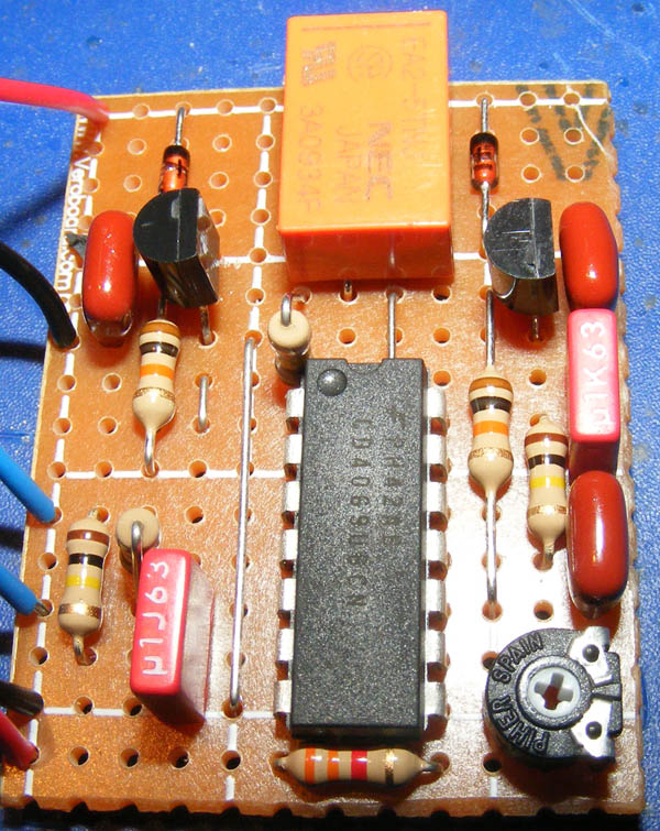
And here’s a picture of my finished circuit. Works like a charm.
Ooh… i found the correct name of the needed switch arrangement: S-R latch (with two individual momentary contacts, one for “Set” and one for “Reset”)
Hey Harald, im slowly working on the “programmable switcher” idea… I´ve found that we need a kind of switching that have individual inputs for ON and OFF states. With a single latch control, we dont be able to “select” the state with the dips… this configuration will only alter the previous state. Maybe the same design configured to perform a “OR” gate will work… not sure.
Here you go: http://www.geofex.com/FX_images/ltchrly.gif
Note that there’s a missing (+V) label at the + side of the relay in this schematic.
Harald,could you link me to the schematic for this?
Thanks,
J.
That is actually quite an intriguing idea. Afraid I don’t have much time these days either, but I’ll definitely keep it in mind. Do let us know if you end up making it 🙂
Hi Harald, I was thinking about this switching circuit and i think that is possible to use some multipole dip switches ( like that: http://www.globalsources.com/gsol/I/DIP-digital/p/sm/1055626183.htm) and combine some of these relay circuit to make a sort of mechanical programmable 8 channel looper… i just dont have the “braveness” to start this alone… :p
There’s not enough room on the board as it is so you’d most likely have to tack on a tiny additional board with just the 78L05 and 2x caps of decent size (47uF maybe). You need three strips, “input” at +9v, ground at center and “output” gives you +5v. Caps go from either +v side towards center and ground.
“I guess when using a TQ2-L-5V it doesn’t hurt to add a 78L05 and a couple of caps, right?”
So how exactly would you wire that ^ up?
Right, without knowing much about that particular relay I’d say that’s a good idea. You don’t want to exceed the voltage limit.
I guess when using a TQ2-L-5V it doesn’t hurt to add a 78L05 and a couple of caps, right?
Hi Jimmy,
Yes you wire it up like you would a regular DPDT mechanical switch using the “SW 1” – “SW 6” in place of the switch lugs. And no, you won’t be able to use a bi-colored LED with this circuit I’m afraid.
This is awesome – thank you so much for your postings – I’m looking forward to trying out some pedal builds! I’ve put these circuits together to build a quiet bypass looper – I was wondering do I wire the board up as if I was wiring up a standard dpdt mech. switch? I was also wondering if there was a way to use this setup with a bicolored led (for an ab box?) prob not possible with current layout – but is this a possibility for the future?
Great work!
I don’t think that relay will work, sorry. It’s a single-coil and you need a double coil. I had a look at the other relays they had and I couldn’t see any that would fit (do keep in mind I’m not an expert at this).
Here’s a link to the one I used: http://www.smallbearelec.com/Detail.bok?no=1011
If you look at the data sheet for the NEC-ea2 you’ll see what the double-coil one looks like.
HEy Harald
Any thoughts on whether this is suitable relay?
It looks to be, but im not sure.
http://www.rapidonline.com/Electronic-Components/Low-Profile-Dpco-1a-5v-Coil-Relay-60-4245
Thanks