When you’re done with the circuit and want to put it all together in an enclosure you need to add some wire. While there are any number of ways you can do this I’ve tried to illustrate some of the more common ones here.
Tip: Test your circuit and make sure it works as expected before starting on this. It could save you a lot of trouble later on.
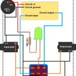
Regular true-bypass
This is the most common way of wiring a single non-buffered effect. If you’re uncertain this is probably the one you want. You can also use this wiring scheme on many buffered effects making them true-bypass instead (just use the circuit effect output and ignore the buffered output).
You’ll also find a wiring diagram including a battery, though I believe there’s little reason to use these now with cheap and readily available DC power supplies. Therefore I won’t include the battery in any of my other wiring diagrams.
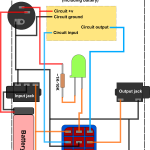
Buffered effect
This is the usual way of wiring a buffered effect that you want to keep buffered (you can wire most as true-bypass instead, if desired). Note that you can get away with using a DPDT stomp switch as only two poles are actually used.
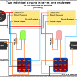
Two circuits in series sharing the same enclosure
Here’s how to wire two independent circuits in one enclosure, both as true-bypass. You have an on/off stomp switch for each circuit which toggles that circuit in and out irrespective of the other circuit. If you toggle both circuits on the signal first passes through circuit 1 before continuing to circuit 2.
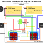
Two circuits sharing an enclosure and you can select one at a time
With this wiring the bypass/effect switch gives you the option of either bypassing both circuits or activating one of them. Which of the two circuits being activated can be selected using the toggle switch. Note that the circuit LED corresponding to the active circuit will only light up when the effect as a whole is active, i.e. it will act as an effect on/off indicator as well. Wiring is true-bypass.
This wiring scheme also works great if you’ve got a two-channel effect (maybe a preamp emulator with two distinct channels) where the toggle switch will act as a channel switch.
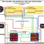
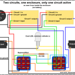
I’ve included two more variations of this wiring using a dual LED in place of two regular LEDs. Note there’s a difference whether you have a dual LED with a common anode or a common cathode.
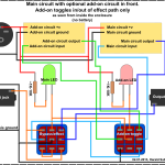
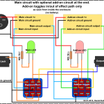
A main circuit with an optional add-on circuit in series
You have a main circuit that you always want to keep in the effect path, and an additional circuit you want to be able to switch in and out when the main circuit is active. E.g. this is one way of including an extra boost circuit with your effect that can be toggled on and off. Wiring is true-bypass.
Note that there’s two different ways of doing it based on whether you want the add-on circuit to come before or after the main circuit in the effect path.
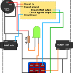
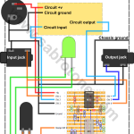
Regular true-bypass, but using the latching relay vero circuit
With this circuit you can use one of those nice “soft touch” single pole momentary on stomp switches in place of the much less elegant 3PDT. You no longer connect the LED directly to the DC jack; instead you wire it to the relay board as indicated (which has an on-board LED resistor and an additional trimmer to further adjust LED brightness to your liking). But you now have to power the relay board itself.
This shows how you wold go about using the relay switch for standard true-bypass wiring of an effect, but there’s nothing stopping you from using it in place of any other DPDT on-on switch (board labels “SW 1-6” corresponds to the soldering lugs you’d find on a regular DPDT).
You can find the latching relay vero layout here.
Hi! I know this is kinda off topic but I wwas wonderiing which blog platform are you using for
this website? I’m getting sick and tired of WordPress because I’ve hadd problems with hckers and
I’m lkoking at options forr another platform. I would be fantastic
if you coyld point me in the direction of a good platform. http://Boyarka-Inform.com/
Hi Luc,
There are many ways you can do this. The easiest way is to use non-isolated witchcraft 1/4″ jacks (those open looking metal types that are quite common), in which case the sleeve will be grounded to your metal enclosure automatically.
When you use isolated jacks, like I’ve started doing, you need to find somewhere else to make a connection to the chassis. I usually solder a wire to the toothed washer sitting on the inside of the foot-switch. Since this is of metal and makes good contact with the chassis, it does the trick. I then connect this wire to my other ground points, thereby grounding the chassis.
Other options could be inside washers for other switches, potentiometers or jacks, as long as they’re metal and firmly connect to the chassis. Supposedly the input jack sleeve is the best point for grounding, but I don’t think it makes that much of a difference in your average pedal.
Sotos,
I’m afraid none of these wiring schemes will do what you want. I may add some more in the future, but no promises. Without having thought this through, I suspect you may need a 4PDT switch, which could be unfeasible.
Hello!
How do I ground my circuit to the chassis?
I see in your Regular true-bypass wiring explaination you take all the ground wires and ground them in one spot on the chassis, how would I do this?
Hi Harald,
It is exactly what I was looking for
” Harald
25 September, 2016 at 18:12
You mean a switching scheme that will allow you two switch the order of the two effects?”
I am making two pedals in one, I mean two circuits that share the same enclosure and I want to be able to change the order of the effects.
Can I use any of the above circuits?
Thanks
This would be great: A logic for two effects in one enclosure, that allows both options, selectable via a mini switch. (a: Two independent circuits in series. Each has a bypass switch b: You can select one at a time. Switch 1 is for bypass, switch 2 selects effect 1 or 2).
http://musikding.rocks/wbb/index.php/Thread/418027-Schaltlogik-f%C3%BCr-zwei-Effekte-in-einem-Geh%C3%A4use/
You mean a switching scheme that will allow you two switch the order of the two effects?
Hi there, Sabro!
is there any schematics for wiring two effects in one box with choosing route fx1 -> fx2 or fx2 -> fx1?
thanks man for your amazing site and sharing your knowledge!
Don’t use solder. Big no!
For jumper wires that span 6-7 rows or less I use discarded component legs (those short metal legs you clip off your resistors and capacitors). For longer jumps I use a single-conductor 24 AWG wire that I strip the insulation off of (you don’t need the bulky insulation when used as a jumper).
Hi Harald,
Thanks for all the great resources you have up on here! Really great stuff. Just a quick one about jump wires – on some of you ‘gut shots’ of pedals the wires don’t have any plastic coating as I expected they would. What wires do you use for these, or do you use solder as I have read some people do?
Cheers! Joe
You basically want to 1) hardwire the buffered bypass switch logic “on”, and 2) wire everything as regular true-bypass while treating the now hardwired input as the circuit input.
Hey Harald,
Love the site!!!!! I am unclear on how to do true bypass to a buffered bypass effect (klon). Could you please clarify? Thnx…
3 circuits on one switch is difficult, yes. But you can put as many as you like in series given that they each have their own switch. If you think about it that’s exactly what a pedal board is, only each circuit has got an enclosure for themselves rather than sharing a big one.
Hi Harald 3 circuits together will not work for one at a time wiring ,what about 3 circuits wired in series , I have seen an enclosure with 5 circuits ?
I wired the boost section after the main circuit on my build, and that boost works very well (though it’s far from transparent at most settings).
I found that the boost does work, but it doesn’t as well as yokîu think it would.
Sorry to hear that, Jasmine. I went over the illustration once more to see if I made any mistakes, but it still looks right to my eyes. I assume you’ve also double checked the switch wiring?
You could try using the continuity tester on a DMM to verify the wiring, or better, inject a test signal on the input jack and use an audio probe (check out the “debugging” section) to listen/verify.
I recently wired up the main circuit with optional add-on circuit in front to the Wriple Treck. Link, https://sabro.no/sabrotone/wp-content/uploads/2013/01/Addon_before_tb.png. The bypass works and the LED comes on when you push the switch, but the only problem is when I press the boost switch the sound doesn’t seem like it’s changing. I looked over the board for bridges, wiring positions, soldering joints, ect. Any help would be appreciated.
Thanks,
Jasmine
Yes, mono jacks for both input and output unless you want to include a battery (in which case you want a stereo jack for the input).
on the schematic that you use mono jack input and output, right?
Yes. You shouldn’t have any problem finding a 4P3T rotary. That should work.
Hi Harald
Thanks for getting back to me. Instead of using 3PDT switches, could this be achieved using a rotary switch or an on-on-on toggle switch? Would still want a master bypass 3PDT switch..
Hi Ken,
Two circuits are a breeze, but three circuits are much more complicated. The reason for this is that your common 3PDT stomp switch only has two states. Using a stomp switch for switching between more than two states is going to require some additional circuitry either analog or digital (micro controller).
I’ve used the “Two circuits sharing an enclosure and you can select one at a time” wiring diagram and it works great.
Would it be possible to update this one to work for 3 circuits? So 3 circuits with only one active at a time?
I’m not sure whether you’re joking or not. You have to explain to me what about SPST wiring you’re wondering about.
Spst wiring please 🙂
Ben,
Haven’t got that kind of illustration since it’s more of a case-by-case problem. It’s typically used in place of normal wire for the input and output in effects that are very high-gain or noisy in some way (LFO ticking etc.). But it’s not always needed in these effects since it’s also a matter of the layout and how the wires are laid out.
If you decide to use it; use the inner conductor as your signal wire (makes sense), and solder only one side of the outer shield to ground.
Hello.
When should shielded be used? Is there an illustration showing how each wire is connected when shielded wiring is used?
Dale
How about wiring for the clickless relay system?