Update (30.11.2017): It’s ironic, having managed to put together a stripboard/veroboard app, I decide it’s finally time to dig into PCB design…
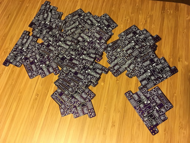
Friends gave me such good feedback on this circuit I decided I wanted to build a small batch and see if I could sell/give away a few somehow. I created 10 complete vero circuits, and half-way through I found out life was meant for doing other things. Sooo boring and time consuming doing more than one! It was time to consider PCBs.
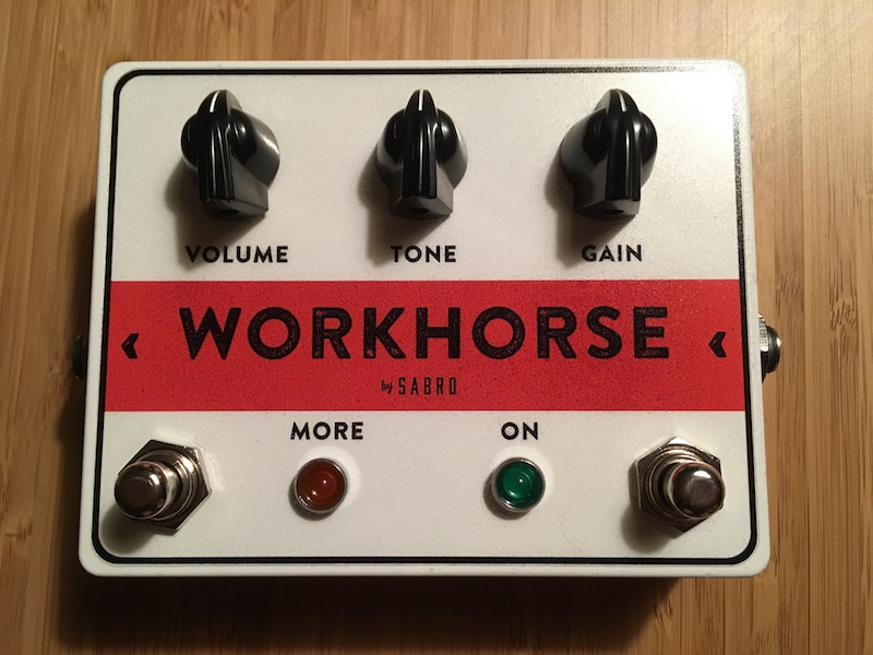
 I went through a few revisions, but ended up with this circuit. Since adding features was easier and more space efficient on a PCB I ended up designing it with u-controller handling of the switching logic with relays and indicator LEDs, meaning I could use nice soft-touch momentary stomp switches 🙂
Also, I’ve included a reverse polarity power supply safety valve that’s a bit more involved than your typical reverse-biased diode, but it actually works, and that’s important now that there are a u-controller in there as well.
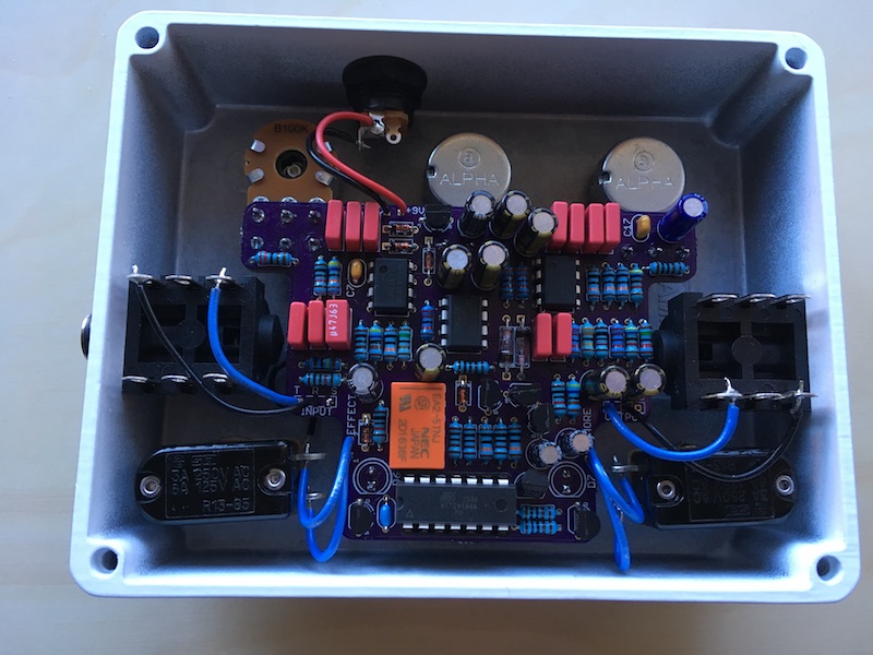
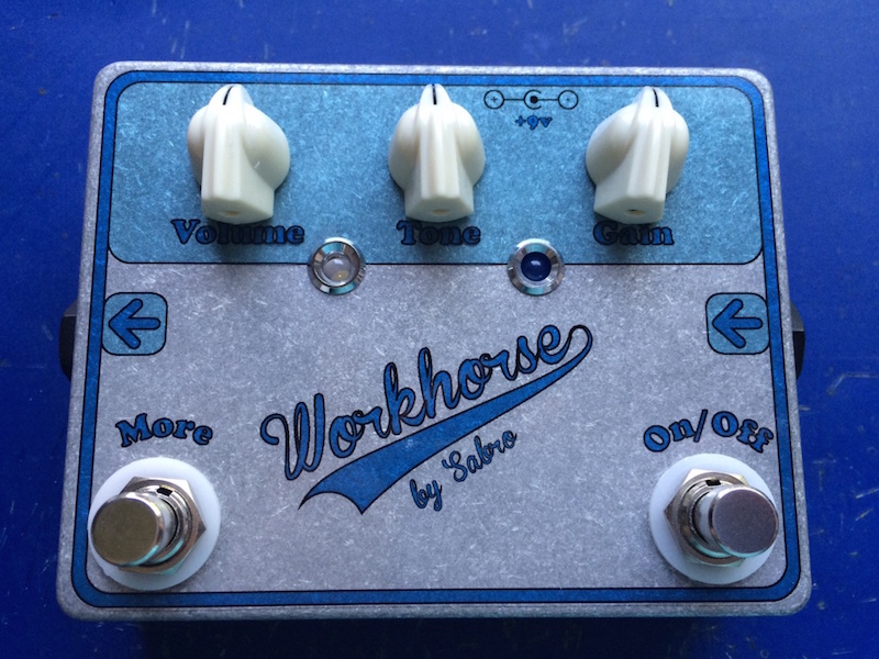
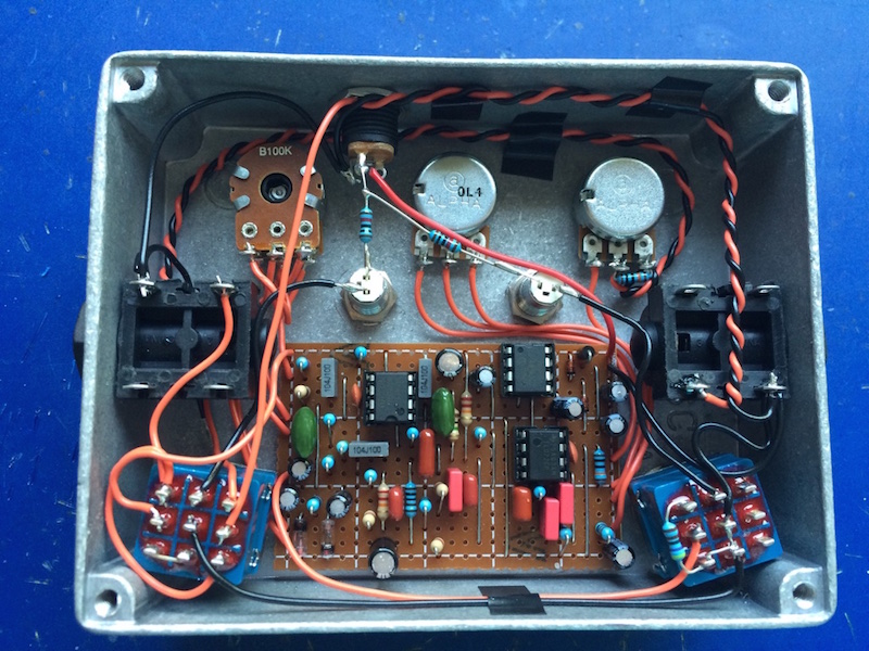
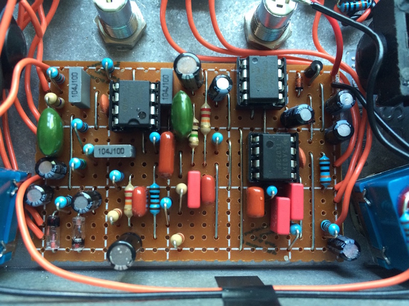
 The board was designed to fit nicely into a 1590BB with just enough space for everything. I love how it only takes a few short wires to get everything together! Here’s one I put in a white enclosure for a change.
I was optimistic and actually printed quite a few boards thinking I might build a few and ask the local stores if they’d be interested, but I haven’t gotten around to that last part yet. I’m struggling with the economic side of things, you can say.
This circuit was originally put together on request from a small independent guitar store in the area. While putting everything together the store went out of business, so the original idea fell through, but I did build a prototype unit which have been very well received within my small circle of friends.
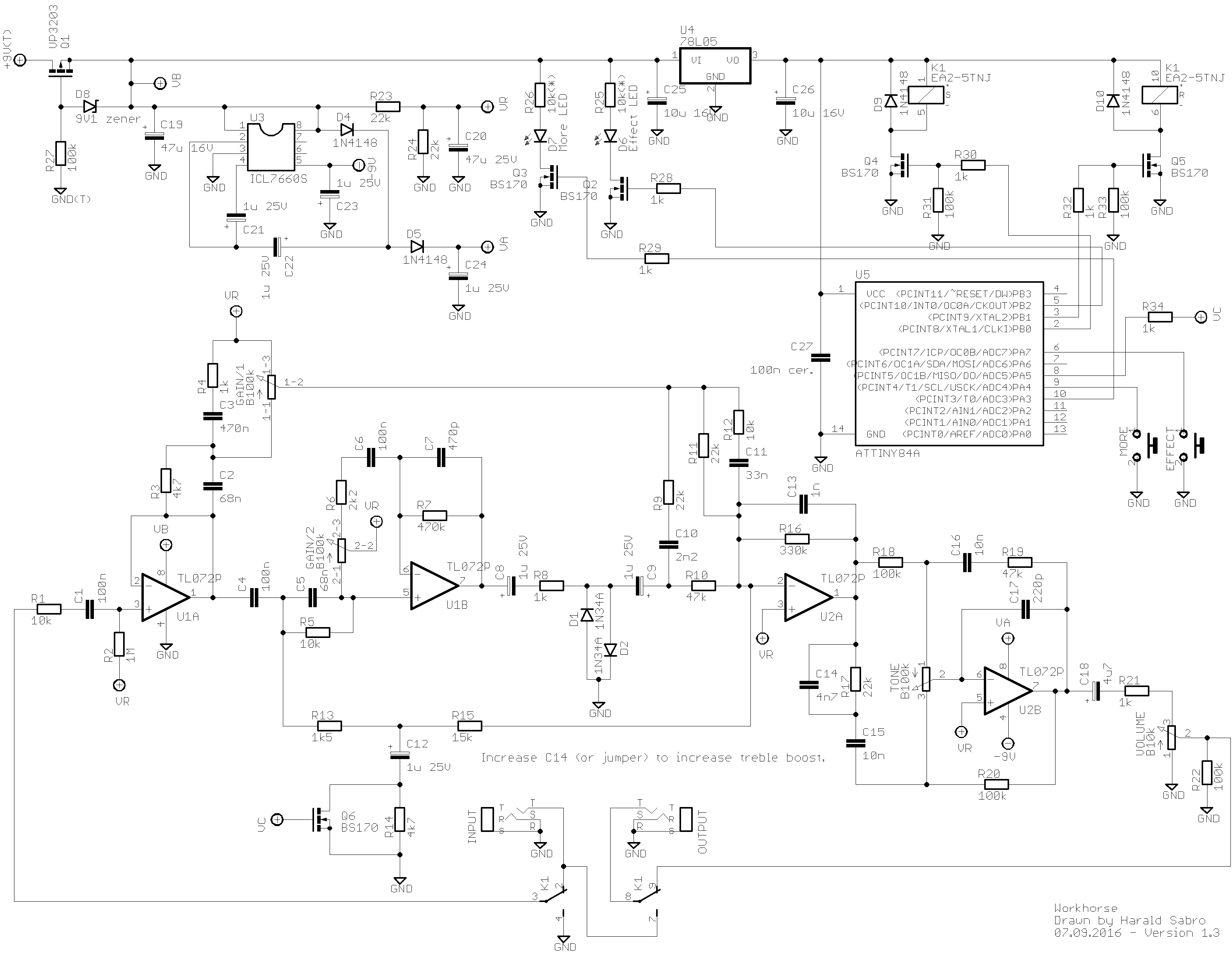
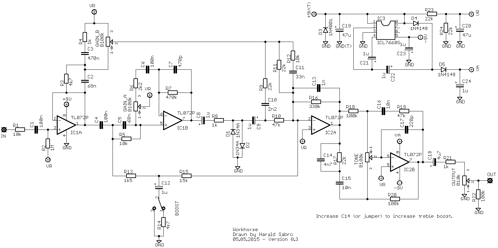 The circuit is, for those of you who recognize it, very much based on the Centaur circuit, which seems to be everyone’s favorite effect these days. But rather than build a number of straight off copies, a discussion with the store about customer requests and demands produced a list of modifications to the original circuit.
– Separate boost.
– Treble boost option, not just treble cut.- True-bypass and no battery.
 In addition to the stated requests I wanted to cut down on the parts count, and use standard values as much as possible, as well as give the effect somewhat more gain.
After some experimentation I decided that with the gain increase, coupled with the inclusion of a new treble control, taking C12 out of the equation by default and bringing it back in for a “boost” worked quite well without affecting the parts count much.
I’ve also replaced the treble control with the treble side from a baxandall tone stack, adjusted to my liking. I know, this actually added more parts, but I liked it so it would have to do.
All in all I am quite happy with how it sounds.
I’ve built only two so far. Ronny Yttrehus of Captain Gone is using one, and I passed the other one on to one of the greatest guitar players in existence (here’s to hoping it actually reached him) just here the other day. I’ve received several requests already, and am contemplating building a few (read “less than ten”), besides building another one for myself. And now you can build one as well!
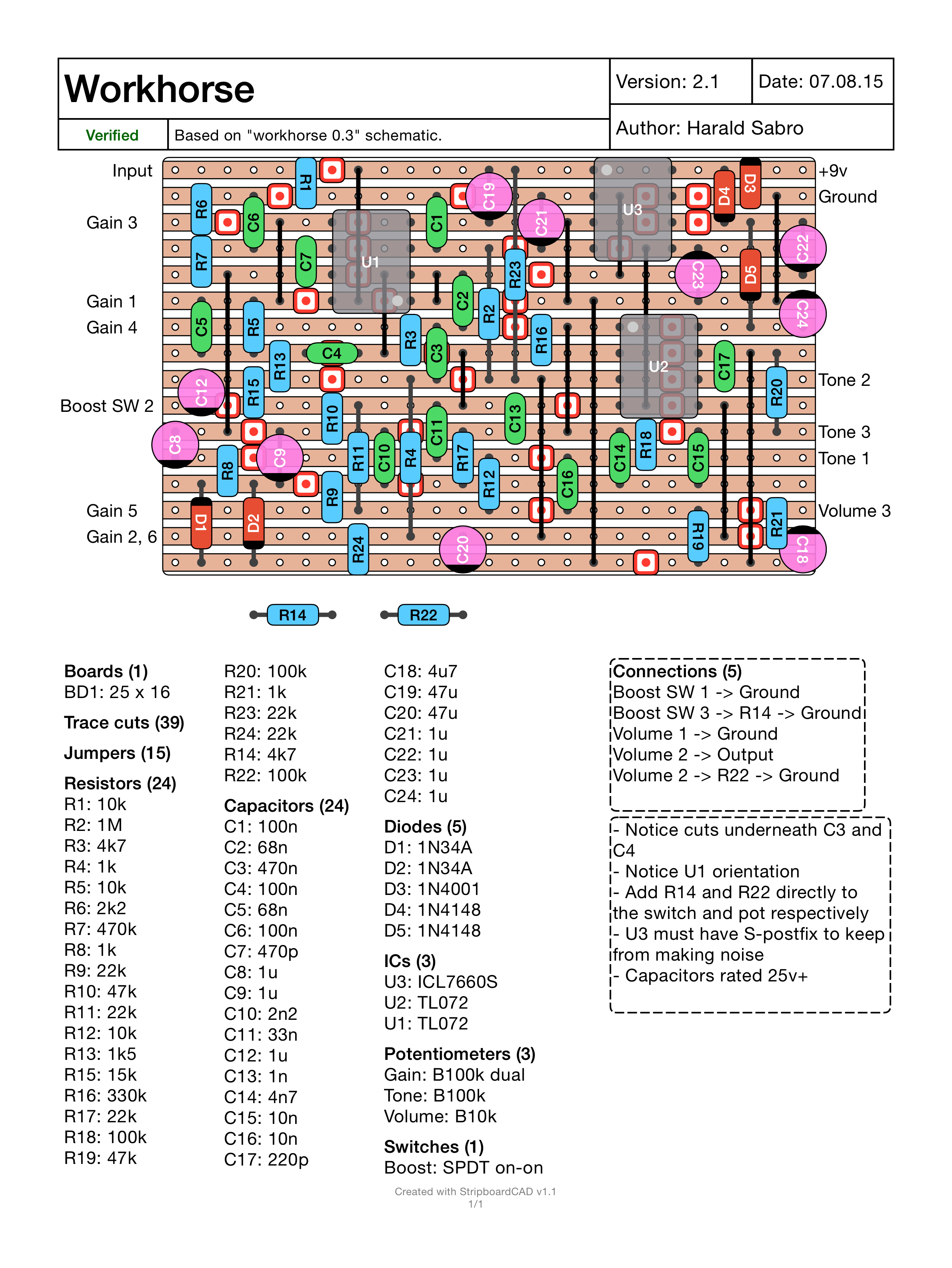
There’s also an extended PDF version of the layout that includes a trace cut diagram amongst other things:
![]() Note: The previous issues with the layout missing parts of the component list has been resolved, and the layout image has been updated.
Note: The previous issues with the layout missing parts of the component list has been resolved, and the layout image has been updated.
Is there any sound clips for this pedal. It looks real interesting.
I’ll consider it, but I want to be a bit careful not promising something (and taking money for it) only to fall short on that promise later. u-controller is short for micro controller (same “u” as in microfarads e.g.), so that would be the avr chip.
Any interest in selling a few printed boards if you have extra? Would need help with the att programming and I don’t know what a u controller is, but your layout and design look fantastic.
Hello Harald,
I’m just curious how this compares to the actual klon. Can you get klon tones from it. This is a very intersecting build. Thnx for everything!!
The voltages should be similar to the Klon, and I do believe I posted voltages for that one.
It’s possible to have ic’s voltage? I don’t have sound from mine. I hear a clock beat from the gain pot…Thanks!
It takes C12 somewhat out of the circuit, a cap that would normally shunt some of the bass to ground, allowing more of the “bottom” of the signal through. You could try a variable resistor here, but I’m not sure how well it would work. Worth tinkering with, though 🙂
So, because I’m a bit dense.. looking at the schematic, the boost isn’t a separate circuit but lowers the amount of signal going to ground, making for more output. The end result is that the boost won’t do anything if the pedal is bypassed, similar to MB’s DeadringerV1 and BoneardV1
Could R14 be replaced with a pot for a variable amount of boost?
The 7660 voltage chip comes in many different varieties. One of the few options that really does matter is the “S”, as without it the chip “works” within the audible range producing an oscillating sound. With the “S” postfix the chip “works” at double the frequency, which puts it outside the range of the human ear, i.e. no annoying oscillations.
Thanks for this creative circuit. The layout mentions the charge pump needs “S-postfix.” What is it?