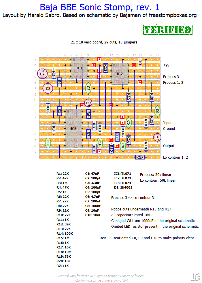
Mat posted a comment suggesting a few effects he would like to see, and having a few hours to kill today I took him up on his request. Here’s a vero layout for the Baja BBE Sonic Stomp. I know nothing of the actual effect box and how it sounds, but I’m sure it’s nice.


Hey there, I’m going to try to build one of these soon, but i will include some modifications, so is there any way you could send me the diylc file for that board, if i redraw it i’m too afraid i’m going to make some mistakes. Hope asking this isn’t impolite but help would be appreciated.
I haven’t tried it myself, but I have received word that others have successfully built it.
Has this vero been updated and Verified ?
Masuto,
I’m not familiar with the circuit at all, but I’m sure you can tweak it to taste.
Hi Harald. Great layout as usual. I must say tho.. My 462 rack sonic maximiser had a bit more bass on tap if i remember correctly. It’s still here somewhere but hes dead. Can i swap some cap to have more lo freq action?
Thanks
Sorry to hear that, Jukka. I haven’t tried this one myself, but several people have built it successfully so I’m pretty sure the layout is good. Have you triple-checked everything?
Has anybody Found the fizzle and low volume problem, I have build tons of pedals, but this one really confuses me, I have trible checked everything. Any help or suggestions World be nice 🙂
Looking at the layout right now and I see this is one of the really old ones from before I realized the electrolytics have a shaded band on them. If you look closely at the cap you’ll notice I’ve added a (+); ignore the shaded band and orient it according to that (+) instead. Sorry about that, Mathew (I should probably go back and edit those old layouts).
So, interestingly enough, C9 is what I have determined is the culprit. If I short the 2 pins of the cap together I have signal. Remove the short and you can hear it fizzle out to nothing. Same on both. I tried different electrolytics with the same result. Finally I pulled that cap and jumpered it and all seems well. Go figure!? If I do a third, I will try it again, just like the layout but the important thing is the 2 I built work!
No shared components. Unless I am blindly staring at a mistake ( which is possible) I got all the cuts. I am sure your layout is fine and this is on my end. Just frustrated that whatever I did, I did twice. I am going to take my dremel and go between the rows and over the cuts again… Thanks for the reply!
From your description it doesn’t perform quite as it’s supposed to I think. I have received several successful build reports in the past so my initial thought is that the layout works. Did you do any substitutions at all, or share components between your two builds (maybe one of the shared components are bad)? Got all the trace cuts etc.?
Well, I built a second one and the exact same problem?! When the lo contour is turned all the way up, I am losing audio at the top side of R19. Also, I have 3.5v on the lower side and 7.7v on the top side when all the way up. 0v when all the way down…
I haven’t got any experience with this circuit at all so I couldn’t tell, but maybe someone else can chime in? It sounds like something isn’t quite right.
I just put this one together and it sounds great but for some reason, when I turn the lo contour up to about half it gets distorted and then cuts audio off all together if I keep going. Any thoughts? Thanks.
changing C8 & C10 you won’t hear any difference in sound. This circuit is only running on 9V and drawing milliamps of current. You can just change C2 to 4u7. You won’t hear a difference if a guitar is played through either 4n7 or 4u7. You will hear a change if you play bass through 4u7, especially a 5 string. The 4n7 puts the cutoff frequency at 34Hz. The 4u7 put the cutoff frequency at .03Hz
Joseph, probably nothing. Go for it.
Hi Harald. Thanks for the layout. I plan to build this with bajaman’s mid pot, and put the input cap on a switch (4n7/4u7) for guitar/bass. I’m just wondering, what is the effect of swapping C8 from 1000uF to 100uF?
Thanks for the info Harald.
My components are arriving tomorrow!!! I’ll post news after I build this.
BR,
Pedro.
Yes, you can use 1N4007 no problem. It’s the same diode, only rated for a maximum higher voltage.
Hi Harald, I’ve recently found this site, and I have to congratulate you for the great work you’ve been doing!
I’m a beginner in this DIY stuff, and would like to know if it’s ok to replace the 1N4001 diode with a 1N4007, which is the only one I could find.
Best regards, and keep up this great work!
I just finished boxing this one up, sounds great! Seems like using quality components makes it sound better than the real one I tried at guitar center. Thanks for the awesome and compact layout, this one is in my pedal chain permanently now 🙂
Thank you! I just finished building this tonight, and it sounds great 🙂
Very happy to hear this! The only important thing is that you found the problem and solved it. Everyone makes mistakes, professionals included 🙂
Rapadi verifies that this works. I just had one pot stuck on 28Kohms, (hmmm).. I compared this to the original, and this thing won. I used better quality components, and the 1000uF C. The 1000u and 100u makes a difference. I’m a electric engineer and I didn’t check the pots, SHAME ON ME.
sorry the Lo countour doesn’t do anything
Well now I got it working, but the proces knob isn’t. I hope that I’m doing something wrong 🙁 … The proces knob does nothing. I will spend time with this. So many have been saying that it’s working. 😛
It may be the layout is wrong. It has been verified, but not by myself.
damn, I couldn’t get this to work. I’m getting a squealing sound and the controls don’t work so well. First time of 80pedals that I did something wrong. Maybe something is broken? any ideas?
please someone contact rapadi@rapadi.net ..
Good catch. Fixed the polarity. Thanks again for verifying, Mat.
Verified! Just reverse the polarity of C9 (as seen on Madbean’s schematic: http://www.madbeanpedals.com/projects/Bloviator/docs/Bloviator_ver2.pdf) and it’s perfect. Many thanks for the great layout!
Incredible! Many thanks. I’m going to cancel some plans tonight and build this up 🙂 I’ll be sure to let you know how it goes.