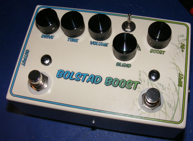
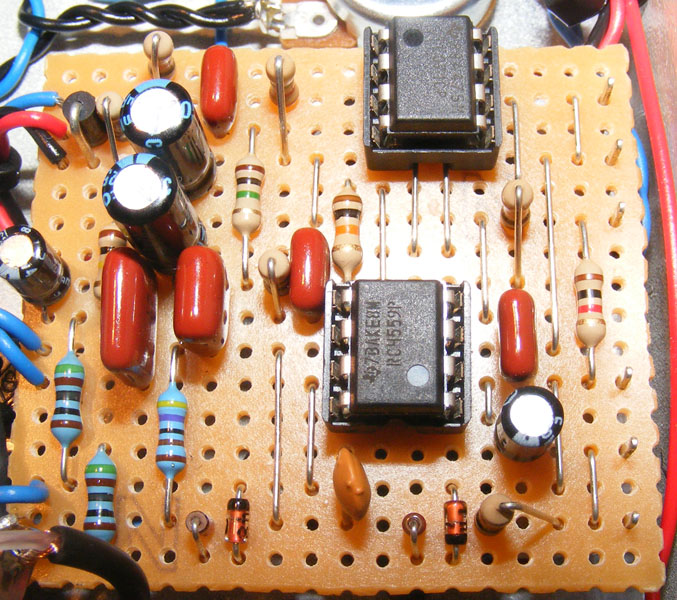
I put this thing together as a gift for a relative recently.
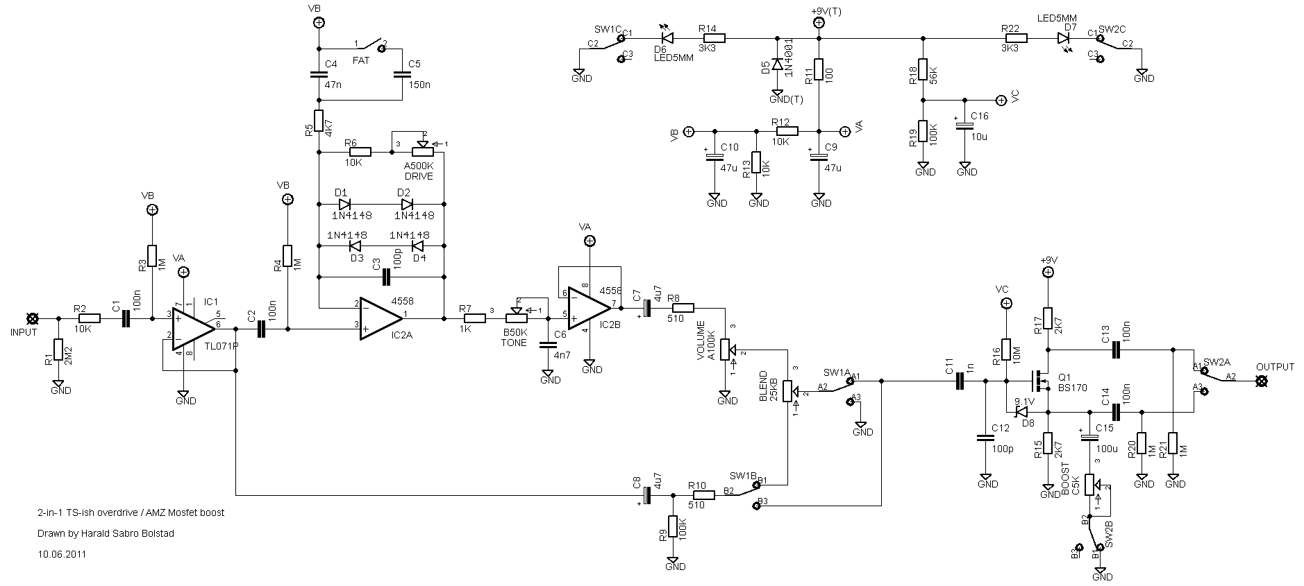
The overdrive part is something I derived from several different circuits; the “Eternity”, the “Zendrive”, the “Timmy” and R.G.Keen’s article on the technology of the “Tube Screamer”. The input buffer was borrowed from the “Centaur” and a blend pot was added to the output to allow a mix of over-driven and clean signal.
The output from the overdrive (either effect or bypass signal) goes straight to an AMZ Mosfet Boost for some extra… well, boost. The two effects are separate and can be engaged individually.
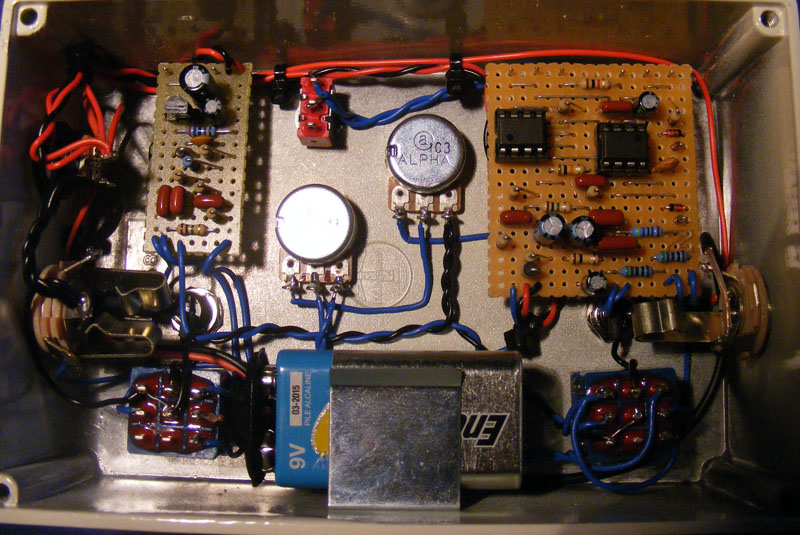
As a side note I tried something a little different this time. I wanted to try board-mounted pots to secure the boards to the enclosure. I used them for the “Drive” and “Tone” pots on the overdrive, and the “Gain” pot on the boost.


Clement, just make sure the switch you have switches in the right way, I have come across with a few that switch with the contacts vertically (instead of horizontally like you have it on the picture). Use a multimeter on continuity to find this out.
Sorry to hear that, Clement.
Your drawing looks reasonable, apart from the input and output jacks.
Now, this could just be image you found and a drawing mistake, but the output jack only need to be mono, and unless you’re using a battery the input jack can also be mono. The input jack has ground wired correctly to the sleeve, but the input signal is wired to the ring rather than to the tip. The output jack has ground wired to the ring rather than the sleeve, and also the output signal wired to the sleeve rather than to the tip.
You use a slightly different 3PDT wiring compared to me; one that does not ground the circuit input on bypass, but that’s not important. It should work fine the way you have it.
Hello once again, Harald.
Unfortunately, i’m experiencing some problems with this layout.
Rewired this baby for true-bypass using 3pdt the way you suggested, but omitting the part with booster just for now. Some signal seems to pass through, but it sounds as silent creaks and screeches. Turning pots does affect the character of these sounds.
Tried debugging. Tried different types of wiring for 3pdt (with negative ground etc.). Even completely reassembled the board, but to no effect.
I would appreciate, if you can take some time to look at the drawing of how i wired the pedal (http://i.imgur.com/M4vvBJE.jpg).
And thanks a lot!
Hi Clement,
The easiest way to make this true-bypass would be to skip the on/off switch, but wire it as if it would be always on. I.e. use “Blend 2” as your circuit output, and wire the “on/off SW 5” point on the board to “Blend 1” (if you look at the schematic it will maybe make more sense). With that done you can “wrap” the whole circuit in a regular true-bypass wiring scheme.
Adding an actual vacuum tube in here is going to be anything but straight forward, unfortunately. And the result, should you be able to pull it off, wouldn’t necessarily sound any better, and possibly might even sound worse. I say it’s definitely, definitely not worth the effort. But if you really want to give it a try, check out the BK Butler Tube Drive to get some inspiration for your new design.
Hello, Harald.
I was wondering, do i get rid of On/Off SW 1-6, if i’m aiming for a true bypass? And, also, is it possible to implement tube into this layout?
Edward,
Start by checking out the “debugging” section. A whole lot of bugs can be eliminated by careful examination. You can get some pointers on what to look for.
For this particular effect I’ve also got the schematic available (somewhere around here), which can be of help during this phase.
If I were to guess I’d say it’s either a missing/wrong component, a solder bridge, or wrong wiring.
Hope you’re able to figure it out.
Hi Harald
Just finished this build
Getting no overdrive
The blend pot is working like a volume pot
That’s the only variation in the signal path when circuit is engaged
Same volume in bipass and effect
None do the other pots or fat switch chage the signal in any way
Any idea where to start on this de bug
Thanks
Ed
Can anyone in this thread help me out with this build? I have it all build up but it is not working right. The Drive A500K pot only works from 250K~500K and the Volume pot works but when it is turned all the way down, it acts as if it is full volume. Ive been slamming my head against the wall about this! Can anyone help? My email is christianterjesen@gmail.com Thank you!
I have never tried or heard a SHO, but it’ll probably sound OK. Hehe, I have no idea to be honest.
How do you think it would sound with a ZVex SHO replacing that booster (with both on)?
Haha, thanks for the compliment. I didn’t come up with that tone control myself though, I believe I nicked it from the zendrive. I also considered the R5 as a pot, but didn’t want too many controls. You’re absolutely right about R1, but I guess this gives you the option of wiring this as true-bypass should you want.
More about the 5k pot instead of R5.
In addition to change the character of sound, it changes the tone. If you don’t want to tune tone for every position of pot, you can use use dual 5k pot to compensate tone. Hook second stage of pot between 3rd pin of 4558 and ground through the cap. The value of cap depens on output resistance of input buffer. I put 150nf and tone compensation works fine. After all pot should be C5k.
Great build, especialy you solution for tone. Original tone was hard to tune, near the start and the end values of the tone knob, sound changed a lot, and from 9 to 15 hours it doesn’t changed much. But with your tone control it changes smoothly all the way.
BTW since you haven’t true bypass here you don’t need R1, throw it away, nothing will change. R6 is very nice too, love low gain. But I think
Also try to put 5k pot instead of R5, you’ll find some new soundings)
I think I’m slightly pro-buffer, but it certainly depends on the effect (and the buffer). For this one I kind of already had the buffered bypass signal available because of the “Blend” pot at the end so a buffered input required no additional parts.
You can wire it true-bypass, but you still need all the components (again because of the “Blend”).
Hi
I’m going to build this od – boost pedal.
I have a question for you.(if i can)
Why did you choose for a buffered switching instead of a true bypass one?
Do you think it is a better switching methode in this pedal?
What parts are to be omitted for a true bypass switching option?
great job Harald
thank you
Peter
Yes, you use the last pole (the last three lugs to the right in your picture) to connect the LED leg to ground.
Connect LED anode (+) to v+ via a resistor and connect the LED cathode (-) to lug #7 on your 3PDT. Connect lug #8 on your 3PDT to ground and you’re good to go.
Hi again..
Tried everything now, it just wont lit up besides when putting the leg to ground.
The wiring is exactly like this
Lug #1 connects to both lug #6 and the output jack tip.
Lug #2 connects only to lug #2 / wiper on the “blend” pot.
Lug #3 connects to ground.
Lug #4 connects only to lug #1 on the “blend” pot.
Lug #5 connects only to n1 on the circuit, labeled “On/Off SW 5″.
(Lug #6 connects to lug #1 as described above).
Look at the picture, i have those 3 lugs left on the last pole but none of them will work, this makes me insane really…
How hard can leds be….
http://dl.dropbox.com/u/2828668/wiring-ts-derrative.jpg
The pole isn’t the same thing as a lug. You have three solder lugs left on your 3PDT (3 (P)oles, (D)ouble (T)hrow), all of which are connected to one pole. The center lug is always connected to the pole, and either of the outer lugs is connected depending on the state of the switch.
Run a wire from the positive of your power source (typically DC jack) via a resistor (1k-10k depending on how bright you want your LED) to the anode/positive/long leg of your indicator LED. Connect the cathode/negative/short leg of your indicator LED to the outer pole solder lug corresponding to “effect on”. And finally connect the center solder lug to ground. This is the usual way of setting up an indicator LED with a 3PDT. Have a look at the illustrations on the “schematics & drawings” page.
Thanks, works great now, besides i can’t wrap my head around how to wire the LED.
When you say last pole im not sure how to do it since i actually have 3 poles free on the 3pdt.
Ive been trying many ways but it ends up in a delay and a pop when switching the circit on/off.
Thanks!
Your wiring description looks correct. Connect the “Input” on the vero layout directly to the input jack. Use the last pole on the3PDT for the indicator LED as usual. If you connect it this way and -do- get bypass sound only I’d start looking for a problem in the main circuit, somewhere between the input buffer (where the bypass sound is coming from) and the blend #3 lug, which is the “output” from the main circuit.
Hi!
Im also wiring this one without the booster but im a little confused.
I just wanna have it with a 3PDT switch and led indication.
If i follow these instructions:
Lug #1 connects to both lug #6 and the output jack tip.
Lug #2 connects only to lug #2 / wiper on the “blend” pot.
Lug #3 connects to ground.
Lug #4 connects only to lug #1 on the “blend” pot.
Lug #5 connects only to n1 on the circuit, labeled “On/Off SW 5″.
(Lug #6 connects to lug #1 as described above).
My only wonder is how to connect the input from vero as well as the input jack.
I tried some ways but everything ended up in one thing.
I get sound only in activated mode, not in bypass, the blend knob works tho but as i said i cant get it to work when the 3pdt is in bypass.
Any advice on this?
Thanks man!
Hi, Marvin.
Let me see. First off, you’ll find an illustration on how I number my switches in the “schematics & drawings” section. Now you want to wire the 3PDT as follows:
Lug #1 connects to both lug #6 and the output jack tip.
Lug #2 connects only to lug #2 / wiper on the “blend” pot.
Lug #3 connects to ground.
Lug #4 connects only to lug #1 on the “blend” pot.
Lug #5 connects only to n1 on the circuit, labeled “On/Off SW 5”.
(Lug #6 connects to lug #1 as described above).
I am building this overdrive without the boost. I am not sure how to wire the blend knob. Also unsure were to wire n1 labeled on/off sw5. I think I know everything else. I currently have it wired up and I get bypass signal and effect signal however they are no different and the pots do not seem to have any effect. Any help would be appreciated.
Thanks,
Marvin
You’re right, I spoke to soon. As I’m slowly getting my brain started I remember I wired this effect for buffered bypass. I don’t have an illustration showing how this was done, but if you look at the “2-in-1[…]” schematic (also under “schematics & drawings”) you’ll see how both switches should work.
SW1 is a 3PDT enabling or bypassing the OD section (regardless of the boost that follows). You can see from the schematic how each switch lug is wired (A1, A2 and A3 corresponds to my 1, 2 and 3 labels, and B1/B2/B3 to 4, 5 and 6). The last pole is used for the indicator LED.
SW2 is also a 3PDT enabling or bypassing the boost. One pole enables or disables the “Boost” pot and one pole selects either bypassed (unity gain non-inverted) output or boost (inverted) output. Again, the last pole here is used for the boost indicator LED.
Sorry for starting you off on the wrong path, my mistake. Hope you get it up and running!
I figured out wiring,but here I’m confused by that blend pot. It says that blend 1 and 2 go to switch pins 2 and 4,and that is different from wiring in “schematics & drawings” . 🙁
Except for the indicator LED this wiring is almost identical. I wire the LED separate from the board though, and that’s about it. But you probably figured that out already from the illustration.
Thank you 🙂 It’s not my first build,but wiring is a bit different than those on GGG http://www.generalguitargadgets.com/pdf/ggg_whrl_lo.pdf?phpMyAdmin=78482479fd7e7fc3768044a841b3e85a
I usually omit these connections in my layout as they’re identical in almost all effects. If you have a look in the “schematics & drawings” section you’ll find illustrations on how I usually connect everything together. Granted, this effect is slightly different, but only because it’s two full effects in one enclosure. (Think of it as two completely separate effects, but remove the output jack of the first effect and the input jack of the second, and instead connect the first effect’s output jack wire directly to the second effect’s input wire). Hope you can figure it out. Personally though, if this is your first build, I would recommend you try an easier build with less complicated off-board wiring to get you going.
PS! You gave me an idea; if I find time in the future I’ll draw up diagrams on how to interconnect several effects.
Can you make a vero layout of this with 3pdt switch,dc jack and out & input jacks,because I don’t know how to conect jacks,efect,switch and 9V. Thank you in advance 🙂
Hi, muhd. That’s a tough one to answer. I guess the easy answer would be somewhere between a Tube Screamer, Eternity, Zendrive and Timmy 😉 To be honest I find it hard to describe; it’s in the tube screamer area. Something that does make it sound a little bit different is the ability to blend the output signal with a portion of clean signal. Nothing fancy, but that was a specific request for this build.
I already gave it away so I can’t really answer you, but I’ll definitely make one for myself soon. Are we talking major, obvious distortion or slight changes to the waveform only detectable with a scope (which I still don’t have)?
yo harald thats a great job! so how does it sounds like?
looks great, Harald! do you get any distortion from the MOSFET with the volume turned up? I’ve found you can get some interesting tones driving a MOSFET stage. it actually distorts rather well. take it easy-
abe.