Having built the Bad Cat Mini II amp, and given how happy I am about that one, I’m contemplating building a 30W Hot Cat amp as well since the schematic is available on schematicheaven.com. But, since these things are quite an investment when it comes to parts and labor I’ve decided to first build an emulator circuit, similar to what can be found on runoffgroove.com, and in the same vein as some of the layouts I’ve already covered (like the Dr. Boogey, JCM800 and Boogeyman).
Here’s my first attempt at drawing a schematic:
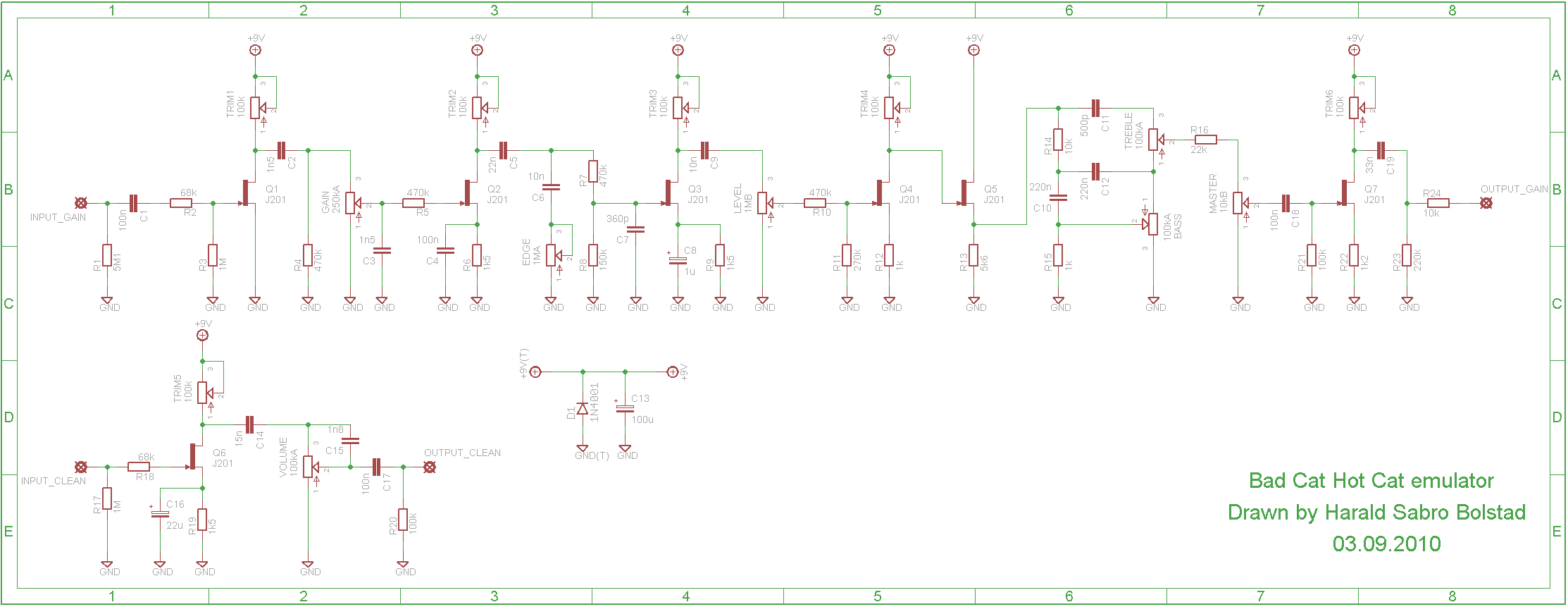
I originally ended the gain channel after the master pot, tuned it to a set of 2N5457 transistors, and reduced the output impedance by a factor of 10 similar to what was done with the Dr. Boogey layout according to gaussmarkov.net, but after building it I was barely able to reach unity gain with all pots maxed. I decided to add the final gain stage leading up to the phase inverter on the gain channel, but also decided to leave this out of the clean channel (as that one was loud enough to begin with). I also switched to and tuned a set of J201 transistors instead. And now it roars! I haven’t tried a real Hot Cat amp, but the gain circuit is quite high gain, and very cool.
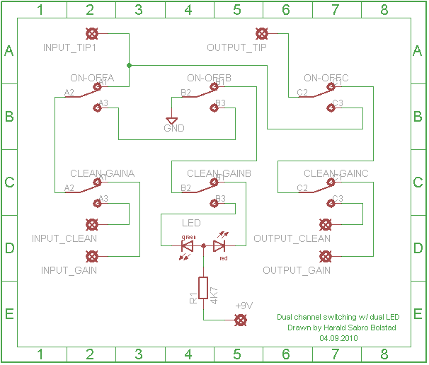
I added a second 3PDT to switch between the two channels (gain and clean) wiring it to a dual-LED. Red is the gain channel and green is the clean channel. Here’s how I wired it:
This is the vero layout I created based on my schematic. I originally created a layout without the final gain stage on the gain channel, but after testing it I retrofitted the last few parts on a separate, small vero board. These parts have been added to the final vero layout.
And here’s the finished build:
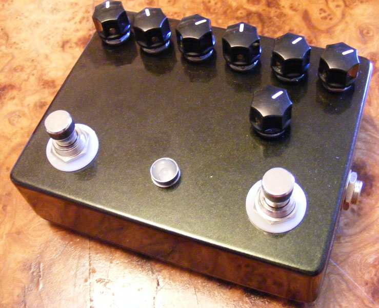
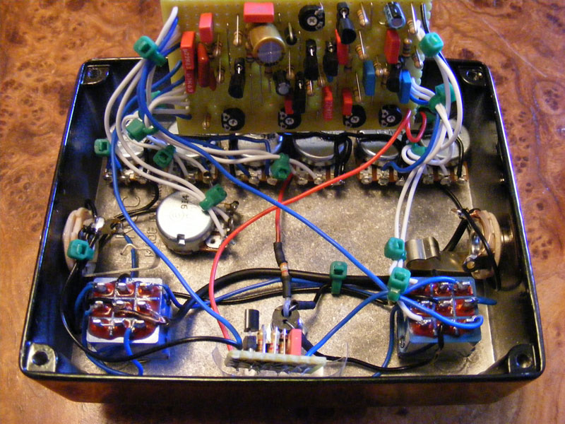
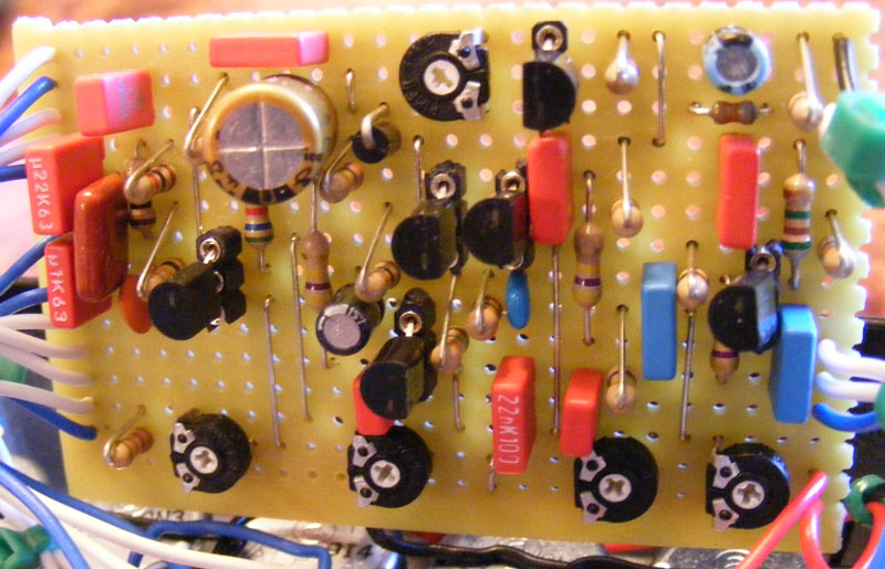
Note that the board pictured is missing the final gain stage, as described above.
The right switch toggles the effect on and off, and the left switch routes the signal through either the clean- or the gain channel when the effect itself is on. The top-most row of knobs represent the gain channel, from left to right is “Gain”, “Edge”, “Level”, “Bass”, “Treble” and “Master”. The single knob on the second row is the “Volume” control of the clean channel.
Update (15.04.2013): A small mistake crept back into this old layout during spring cleaning. Corrected the cut count, hopefully for the last time now 😉


That’s super, Sebastián 🙂 Happy new year to you as well!
Harald! Have a happy new year.
I write this message to say that I’ve built this preamp and the DR103 one on PCB with Fritzing using the SMD version of J201’s.
Only have to say… What a great job you did with the schematics!
I’ve switched the preamps and their channels with DPDT relays (yes, i´ve switched the caps from DR103 with a relay), and put the entire system on a handmade head and cab with a bridged tda2030 power amp (30w, +-15v), now I have a winner amp! Thank you!
Hi Wes,
From what I can remember the gain channel was adequately high-gain when I built this. Q6 (without actually referencing the schematic/layout) will always stay at +9v since it doesn’t have a trimpot, but is directly connected to power, so this is as intended.
I just finished this build and, as far as i can tell, the clean channel works exactly as it should.However, the gain channel is not high gain at all, more like a very small overdriven boost. The master control also doesn’t seem to be doing much. Do you you have any idea what could be going on or am I just missing something? Also, I have no way of biasing Q6 to 4.5v like the others. It always stays about 9v.
Demian, should be safe enough to run this on +18V. Just remember to bias the JFETs accordingly (+9-10V maybe?). And this should definitely increase the headroom of the effect.
Hi,
I’m planning to build this preamp but I was wondering if it would be safe to run it at 18v?(given the fact I only use components that are rated +18V)? And if so, would it yield the typical increase in headroom ?
Hi Tim,
The clean channel is a very basic single FET boost. It’s not going to give you much of an overdrive sound, but it will certainly color your sound somewhat.
The dirt channel can be separated from the clean without much trouble.
Harald,
how is the clean channel on this? Will it get you into a bit of overdrive when you push it?
Do you think it would be possible to simplify the pedal to only have a dirt channel, or are the two channels too integrated to be separated?
This does not have any speaker simulation; it’s a straight up FET conversion of the preamp only.
If I wanted to use this as an amp sim running direct to PA, would I need to run it into a speaker sim first. Does it have a built in speaker sim?
Drain
Are voltage readings taken from the the gate or drain leg?
Thanks Harald
I just finished the W****** twipple Feck…hahahaha
It sounds fantastic. Great dynamics in that pedal. About to finish the Bad Cat.
Dale
Hi Dale,
Yes, that’s correct. It was something I tacked on to an earlier layout.
Harald.
If I read correctly, the ‘little board in the gut shot is not needed with the vero build.
Is that right.
You have some really nice projects. Thanks for the sight.
Dale
It only outputs at most a few volts worth of signal, but if that’s something your power amp can use then you should be fine.
Can this be used similarly to a real preamp? I ask because I have a pretty good rack mount power amp that I’ve had sitting around for ages and I don’t like the preamp I have. This seems like a fun build for when I move to more advanced stuff and I’d finally get to use this power amp.
Noise/hiss on the edge pot? Maybe some DC is getting to the pot through C6? Try swapping out C6 as it might be leaking. You could also try a different pot if that doesn’t work.
ooohh im so sorry mr harald.. i mean edge pot..when u increase it i hear some noise (hisssss)..
can u suggest me what to do..??
:p
I think I understand from your explanation. I will do more searching and see what I find. Thanks for the quick response. Great site! I’m afraid I will be spending a lot of money on parts in the next few months…
Thanks
Hehe. I was just about to dig out that old post when you beat me to it. It’s probably not the best explanation, but I hope you can figure it out.
Sorry – I meant the MarkIV build….
Harald
Please accept my apology. I was reading the comments on the hot cat build and see that you already explain this process with the audio probe.
Thanks for the excellent site.
Harald
I am interested in learning to tune by ear using an audio probe as you mention in one of your answers. Is there an easy answer as to how to do that? Maybe you know of a link to something that explains it in detail?
Hi Mr. oby. I assume you’re referring to a real Hot Cat amp since you’re having issues with the presence pot. I have to admit I’ve never touched or even seen one of these amps before and I’m unable to help you. The simplified circuit you see here is pretty much a straight port based on a hot cat schematic floating around on the net. Sorry.
hmm may i ask sir..
i have problem with presence pot..when i use bad cat with tubescreamer ts9 and i increase presence pot, i got hiss on it..
if i decrease presence pot the ‘hiss’ is gone,,
can u suggest me what to do?
thanks before..
🙂
You are welcome 🙂
this is a nice project.. i was build it and…WOOOOWW sound is good..
thaks mr harald for this.. keep update everyday..
🙂
~indonesia~
Good question. It’s been quite a while and I really can’t remember, but yes, probably in the region 4.5-5.5v. I tuned mine by ear using an audio probe at each stage.
Cool project! What voltages did you end up with on the trimpots? Somewhere around 4.5v?
thanks!! I’ll wait for the soundlips…it seems to be a high-gain beast as far the schem is concerned!!!
When I was playing with this I added one of the triodes in the PI to help remedy a really low output signal. I later swapped the 2N5457’s I was using for J201’s which solved the gain problem, and I left the last stage in. You might not need it using J201’s, I don’t know.
As for the schematic you’ll find it in the “Schematics & drawings” section. It’s an almost straight port from the factory schematics that’re floating around. Good luck with the PCB! 🙂
And no, I still haven’t got any sound clips. It’s on my to-do list.
hi harald, very cool diy site…I was about building the Hot Cat, but i don’t use veroboards!!! Can you send me the schematics?? I’m gonna do a pcb!!!
but, from where did you take the last gain stage? it is not on the schematics of the bad cat preamp!!!
A friend of mine asked If I could build one for him… have you got any soundclips on the pedal? I’m very courius!!!
cheers, francesco
p.s. sorry for my english!!
Yes, you’re almost correct. I used a shielded wire from the on/bypass switch to the output jack to reduce noise/oscillation when using the high gain channel (the channel switch is on the right side in the gut shot picture). I also connected both sides of the shield braid to ground; one side on the output jack ground lug and the other side on the center lug of the 3PDT (which is always grounded according to how I wire my 3PDT switches), but any two ground points should be OK I guess.
I have a question regarding your build, i can see that you use a shielded wire (seems to be to connect the switching channel 3pdt to the output).
Do you wire both sides of teh outer braid to the ground or only one ?
As you know I’m working on the Boogeyman, I fixed yesterday the problem I had on the signal path (a bad solder making contact between 2 lines of the board), but know I have a kind of hiss, increasing with the amp volume. I guess a shielded wire would solve this ?
Thanks
Thanks for your answer Harald
I’m doing the same with my boards but as you say, I’ll try to figure something more satisfactory.
Happy new year !
Denis
Hi, Denis. Happy to hear it.
As for fixing the vero board to the enclosure I still haven’t found a method I’m really happy with. So far most of my builds have ended up with “floating” boards secured with foam and a plastic sheet. This works, but isn’t an elegant solution. My last two builds have been fastened the board face up to the back of the potentiometers with double-sided tape. Not sure how that works out in the end, though.
hi,
I lately discovered your site, i love it.
I’m planning to build this Hot Cat emulator and I have a general question, how do you fix your boards into the units when you have components underneaf ?
Thanks
Denis