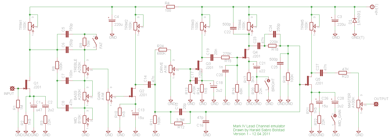
Based on a schematic of the Mesa Boogie Mark IV I found floating around the Internet and the owner’s manual I put together a schematic of the lead channel adapted for FETs. And of course a vero layout as well. I’ve successfully built this (though I haven’t gotten around to boxing it yet) and it sounds really nice.
I’m curious as to how the crunch channel sounds and I might do a layout for that one as well. We shall see…


Just built it on the breadboard, sounds very good, thanks a lot.
I’m thinking about putting it on pcb, does somebody have a layout for the pcb?
Hi,
I simply can’t find the j201, could you suggest me some alternatives?
Hi Harald,
great schematic, I only have one problem, I can’t get that much gain from it.
Could it be caused by the fact that I am using 2N5457 and not j201?
I don’t know how it should sound, should it be high gain?
If the low gain is caused by the 2N5457, could you suggest me an alternative since I can’t find the j201, please?
Do you have some general tips to get more gain out of it, by adding/replacing components?
Anyway great schematic, thanks again
Hello there,
I know it has been a while and this is an old layout. I built it like 5 years ago, it sounded incredible. I stopped using it for a while and yesterday took it out of the box, connected it and it still sound good, excepr for a farty sound that it is making.
Any idea of what it can be?
if it sounds good then it is good regardless of what people say obviously, just curious
why do people keep telling me that this wasn’t converted properly? I keep being told that it was done with an improper understanding of converting preamps to fet circuits somewhere in DIY stompboxes.
I’m having trouble to get this one to work right – everything works, the FETs are properly biased, yet I can’t get a lot of distortion out of it, more like a maxed overdrive pedal rather than the Mark IV high-gain. When everything is maxed I get enough gain for that 80′ hair stuff, even with high output pickups.
Do you have any idea what could cause this lack of gain?
I have not, but I’m sure it’ll sound even better 😉
amazing! just built and biased it and I’m going to box it up tomorrow, have you tried using it at 12v’s. I know some of these circuits benefit from a little added headroom sometimes.
Great news, Mortua.
Sorry I didn’t get around to answer your first post in time.
Well, its working completly now. The bass potentiometer was bad and I missed the 270k resistor :/ One thing I changed because I dident think the bright switch did much use was to solder a 47n to lug 1. Otherwise its sound great and will definitely be in the rig.
Next build will be the Hot Cat 🙂
I build this but have real issues with it. The brigth switch, bass, middle and drive pots dosent work at all. I have sound, a smooth overdriven tone. All trimpots/fets has correct values, but then I trim trimpot 3 and 4 nothing happens with the sound, same overdrive, but the values changes of course:) Any ideas what is wrong? Regards Mortua.
Thanx for answer. I finish this one tomorrow =)
Hi Mortua,
Either 10u or 22u would do just fine.
c16 and c21 should be 15uf….I cant find a 15uf electrolyt at any store. Can I use a 10 or 22uf? I found 15uf tantalum caps, can I use those?
I knew I should have just trusted the layout. You’re right – didn’t notice the u47, not 47u in the schematic. Sorry for wasting your time. I’m kinda glad the component labeling wasn’t the same. It made me trace through the schematic and layout logically and learn a little more.
Almost finished with this one. Going to be a tight squeeze with all the pots and switches! Used to own a Boogie – kinda miss it. Maybe this will give me a taste of the old Boogie tone.
Thanks man!
Very clever of me not keeping the same component labeling between schematic and layout *cough*. Looking at it now and it is indeed correct (notice how it’s written “u47” and not “47u”; the position of the u is the decimal point), but there’s really no reason why you have to use electrolytics here, regular caps of 470n and 220n will do fine though they tend to be bigger and more expensive at that size.
Hi Harald
I’m about halfway through this build and just wanted to check something before I proceed.
In the parts list on the layout, you have C15 as 0.47u and C19 as 0.22u. On the layout, they are shown as electrolytic caps. I looked at the schematic it seems that the corresponding components are C1 and C21 which are denoted as 47u and 22U respectively.
Should C15 be 47u and C19 be 22u? I would have just jumped in and used the 470n and the 220n as indicated in the list but you used an electrolytic symbol on the layout so I just wanted to make sure before I soldered them in.
Thanks
It’s been such a long time since I made these two I can’t really recall what they sound like, but they’re both based on high gain preamp circuits made by the same company so they’re probably pretty similar. I spend too much time making them and not enough playing them really 😉
Hi Harald, I just built this yesterday using J201 and it sounds really nice.
However, I also had built a Dr. Boogie in the past using 2N5457 and do not see that much difference.
As I currently do not have it to directly compare the two units it might be my memory tricking me.
I “think” that the Lead channel comes close doing rhythm stuff but is a little more “singing” playing single notes with Gain and Drive to the end. Is this true ?
wow very nice!!
has anyone finished this project or any demos would be appreciated thanks
gutshots anyone? 🙂
Hey, I appreciate you taking the time to look at my project!
I’ll definitely will add an EQ post distortion, you just gave me the idea of adding some compression also for the pedal to get closer to the original F**N Mark V.
I’ll keep you posted!
That’s great, Giorgio. You have excellent taste in music 😉
As a start, once you know what amount of resistance properly bias each individual JFET, you can swap out each drain trimmer with a regular resistor. Just remember that what works for biasing one JFET might not properly bias another one.
You can also try different JFETs with the same pinout configuration. 2N5457 seems to be a popular choice along with the J201. Maybe a combination?
Given that the schematic/circuit is a solid state adaptation of a tube preamp I don’t think you’ll ever get the exact sound, but you might get close. Those tubes do generate some harmonics and compression that the JFETs lack.
You may want to stick an equalizer at the end of the circuit to get the same post-distortion tone shaping capabilities of the Mark IV.
Good luck, and give a heads up when you complete the project!
Thanks Herald, I am trying to replicate John Petrucci ‘s sound from your schematic as you can see here:
http://ihfx.wordpress.com/2011/08/24/getting-john-petrucci-mark-v-tone-with-jfet-and-opamps/
Thanks for all your updates!
Giorgio
Great Reza 🙂
Thanks a Lot! it sounds now. very nice tone. love your Vero’s )
And there’s your problem. Those trimmers are used to bias each FET, and once you got them all set correctly you’ll get sound. Now, as for the biasing, it’s pretty straight forward once you get the hang of it. As a ballpark adjustment you can start by setting them about halfway and see if that gets you there. You want the drain of each FET at approx. 4.5-5v, but the exact bias will vary with each FET.
But the approach I’ve found to be the best is by using an audio probe and tune each FET by ear. If you search http://www.geofex.com for audio probe you’ll find out how to make your own. Now inject a signal into the effect (guitar strumming/some CD etc.), connect your probe sleeve to circuit ground and a speaker of some sort (watch the volume as this can get pretty loud), then listen in on the drain pin of the first FET. Now tune the first trimmer until you get proper sound through the first FET. Repeat the routine for the other FETs in consecutive order.
I believe there’s also some info on biasing FETs on http://www.runoffgroove.com if you search that site.
Oh, and you can use 2N5457s. They may sound a tad bit different and have less gain, but will work fine (and I am pretty sure they’re the same pinout as well).
and in what exact positions should trimmers be?
Hi
i’ve built this vero exactly but it’s not sounding at all. the only change i did was replacing the j201’s with 2n5457’s. j201’s are very rare here around. can they be replaced at all? please advise me what to do to make it work…
is it not sounding because of the replacement transistors?
sorry, i’m a beginner.
Thanks for the suggestion. I’ve put it on my somewhat long list of things to have a closer look at 😉
Sabro Hello, excuse the inconvenience,
I wanted to recommend another project, Emma Reezafratzitz.
It ‘s the distortion that most impressed me and my opinion and many other connoisseurs, exceeds B. famous DR.
It also has the advantage of having a more stability and therefore do not require the use of shielded cables.
You place the link:
http://www.megaupload.com/?d=N7FRET62
The only error in the key is that the IC 4069 and there isn’t a resistance of 2.2K for the LED.
Sono sicuro che i lettori del tuo forum li farai sicuramente contenti!!!!
Hi Matteo. I believe I get the gist of what you’re asking.
The Mark IV lead channel is high-gain, but not as aggressive as the dual rectifier (“Dr. Boogey”) I think. I didn’t have any feedback/oscillation issues with my circuit, but you have to take the usual precautions common to all high-gain circuits. Keep leads short and direct, keep input and output separate etc.
Good luck! 🙂
Sabro Hello, I note with enthusiasm that you did another Hi-Gain preamp Mesa …
Should have seen that many sound variations with respect to the doctor, I ask you kindly give me some notes on more …
Even this aspect has the usual problem of feedback that damaged the doctor?
As distortion is the level of the doctor?
I look forward to some your clarification.
Bye bye