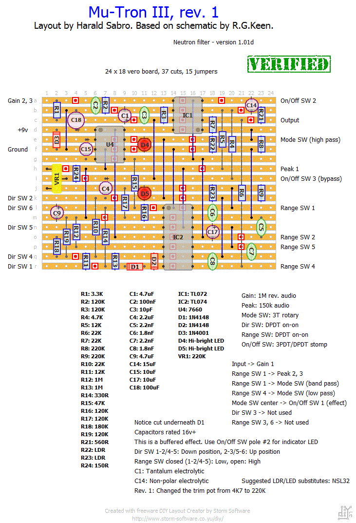
This is my take on a vero layout for the classic Mu-Tron III auto wah / envelope filter based on the “Neutron filter” by R.G.Keen of geofex.com. As usual the layout has yet to be verified, but I’m fairly certain of its correctness according to the schematic.
Update (11.10.2012): Finally, a year later… Nobody can accuse me of being quick!
So after a few nights of poking at this I was finally able to get it working. Both the NSL32- and my homemade optocouplers required a much larger resistance than the 4K7 trimmer originally called for. Supposedly this is down to different specs on the optocouplers I chose to use. A 220K trimmer should give a lot more room for tuning this thing.
I would classify this as a challenging build because it’s so component sensitive. Now you know 😉


Can someone clarify for me where exactly to connect:
(I am using 7660S for +9 and -9V)
Battery negative
Battery Positive
Stereo input tip
Stereo input ring
Stereo input sleeve
Output tip
Output sleeve
Please be specific and tell me exact circuit identifier number,. I’m using this circuit schematic. Any help will be amazing
http://www.generalguitargadgets.com/pdf/ggg_neutron_sc.pdf
Can anyone share a gut shot for off board wiring? This would be very helpful, thanks!
If it’s any help I tried both a 100k and a 250k, and I seem to recall sticking to the 250k. No idea where you can find a 150k, sorry.
Can some one tell me where I can source a 150 k audio pot for this build
Thanks
Ed
Hi Harald, Jose
Trying a 7660S and it´s working !
Thank you !
Bernard
I’m going to say the same as Jose. Get a 7660 chip with an “S” in the post-fix.
Hi Jose,
Thanks for reading my comment !
In fact I used a MAXIM ICL 7660 “CRA 1113”. Don’t know what it means, but surely no mention of an “S”.
I will follow your advice and get one “S” 7660.
I’ll tell you if it’s working better.
Thank’s again.
Bernard
Hi Bernard, yeah, your wiring is correct so the problem is not there. Can you tell us the exact IC that you’re using as charge pump? If should read something like *7660SCP*, being the “S” very important, if your ic is a *7660C* (no “S”) you won’t get rid of the whime.
THe solution is easy: get a 7660SCPAZ, dirty cheap on ebay, and enjoy this wonderful effect.
Hi Harald,
And happy new Year !
I’ve built the MuTron III following you layout and it works great … but … I have a very noisy whine !
Reading the document of R.G. Keen, it seems to be the 10 KHz pulses comming out of the charge pump provided by the 7660 !
I have connected the (-) of the 9V battery AND the Ground signal from the Jack’s in “f1” location (Ground). Is it correct ?
How to fix it ?
Bernard Armand
Paris
luis,
“Input” goes straight to your input jack tip, and “output” goes to your output jack tip. Easy as that.
To hook up an indicator LED:
– LED resistor (4.7k as a good start) connected to DC jack +9V.
– Other side of LED resistor connected to LED anode (+).
– LED cathode (-) connected to on/off switch lug #4.
– On/off switch lug #5 connected to ground.
Hope that helps 🙂
Thanks for this Haralds, please need an help with the wiring, i dont know where connect the input and output of the board, also i don’t know how connect the indicator led in the 3pdt.
http://s279.photobucket.com/user/lbanda1974/media/MutronIII_zpsd24c2c12.jpg.html
thanks in advanced.
Looks great, Jose 🙂
Hi again Harald,
Finally boxed this pedal, and would like to share it with you. Just a comment more. The sound using the GL5549 was good, but erratic. Don’t know by but when changing gain / depth / mode settings, the behaviour was erratic.
Built some hand made octocouplers with several ldr values, and finally hit the nail with the GL5539 ones (40-100k light – 5M dark) and two high bright clear leds from Tayda and a 20k multiturn trimmer.
Now the pedal sounds INCREDIBLE on all settings and verbatim to any demo you can watch on youtube.
Here’s the pedal, hope you like it:
http://guitar-fx-layouts.42897.x6.nabble.com/file/n3535/mutron_ok.jpg;cid=1367654208880-843
BR
Happy, happy! I must have lost a lot of hair getting this circuit to work myself. Congratulations 🙂
Hello again Harald,
It worksssss! I used GL5549 ldr’s.They are marked as 100-200k light /10m dark. Leds are 5mm red water ultra bright from Tayda.
The problem that I had (besides the reversed TL072) was that I used a 500k trim, in oder to avoid problems, , as you had to use a 220K one.
Well it only appeared to work slightly when set full clock wise, so I soldered a 20k new one, and after a little tweaking, it started to work like a dream. Maybe a 10k could offer an even easier tweak.
Thanks again for such a wonderful layout!
My bad, TL072 was not upside down :P. Well, now it sounds and all knobs are responsive. Have now to deal with the trimmer to see if these ldr’s work.
BR
Jose, check the orientation of IC1. That should be IC1 pin8 connected to the 7660.
Hi again, Harald,
Yesterday I built the circuit and failure! 🙂 Well, I get very strange voltages on U4 (7660), about 2,25v on pin 1 and pin 8, and from here, bad voltages anywhere else.
I see that Pin 1 and 8 from 7660 go directly to TL072 pin 4 (-VCC) and not sure if this is correct, in Madbean’s Nautilus (very similar) Pin8 of 7660 goes to ground, but no way connect to fisrt opamp.
The fact is that the leds don’t even lit ( – up row, + down row?), but it hink that theres a problem in the 7660, as voltages don’t seem very correct.
Any hint?
BR
Thank you for your quick answer, I’ll let you know about the progress, let’s hope it all goes ok 🙂
BR
I had success using the “9200” model from smallbear: http://www.smallbearelec.com/servlet/Detail?no=711
As you can see it’s (10k-50k) – 5M, so yours will hopefully be fine. Do note that I had to swap out the trimmer with a much larger one (220k).
Hi Harald,
I’m interested in this build, but I have a doubt about the octocouplers. I’ll try to build it with LDRs and leds first before to spend a fortune in Vactrols or NSLs.
For what I can red at some places, the LDR should be something like 50k light – 10M dark, bur in Keen’s Neutron pdf he also recommends 100-200k light – 10M dark.
I can get a bunch of 100-200k – 10M with no effort (just in my local store), but 50k-10M would need to place an international order if I don’t want to pay 5 euro for each LDR.
Can you tell me which values did wotk for you and if you think that the 100-200K-10M will do the trick?
BR
Ah, I haven’t looked at this one for a long while. No, not working yet, but I’ll see what I can get around too.
Any news here? Did you get it to work?
Hi, Gary. Thanks for letting us know. I hope you figure out what the problem is.
Hi there,
First off, great website!
I’ve built the MuTron but can’t seem to get it working. The voltages are correct, and I can get a signal off D1 and D2, but nothing at the output (unfortunately I dont have a scope)
I suspect it may be the opto isolators that I used, never the less I’ll keep trying to fix it.