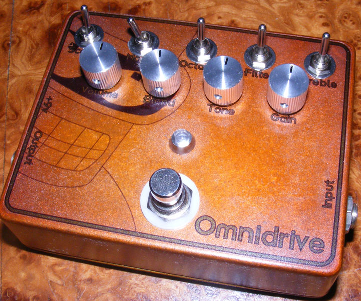
Here’s a vero layout for the Omnidrive, designed by John Hollis.
Update (11.01.2011): Added a missing cut underneath R7.
Update (20.01.2011): Built the Omnidrive circuit today and had to rewire the Gain, Tone and Blend pots. I’ve also updated the layout with what I believe to be the correct switch positions.
Update (14.07.2011): I actually did this some time ago, but forgot to take pictures. This didn’t come out as nice as I’d hope to, something about the dark color of the enclosure, and to be honest I don’t think it sounds fantastic either. It’s certainly a versatile effect with lots of options, but there’s something undefinable (by me at least) about it that I don’t like. I’m probably just colored by my disappointment in how it came out visually…
Update (18.12.2012): MG discovered a slight discrepancy in the “Gain” pot wiring. I’ve updated the layout now with only “Gain 1” connecting to the mode switch, not “Gain 1, 2”. Thanks for noticing.


Happy to hear to found the problem, dizaar. And sorry for my slow response.
Hi, one more time – i`ve traced a layout one more time and found a mistake – 10k instead of 1 k on the output of dist section. Sorry for my inconvience.
I got a question about this build. I`ve tried it and this is a result – two sections (Boost and Filter) work perfectly, but Octave and Gain don`t work properly. When i`m measuring signal at point K11 and E11 – i see at oscilloscope distorted signal. And after R18 and D2 i see the same signal as undistorted.
In resulting sound i don`t get any distorion.
Is it difference using 1n4148 instead of 1n914 diodes?
Nope, just to the mode switch. At least that’s what I read from the layout unless I’m missing something.
Do you have your Gain 1 going to the board as well as Mode Switch 3?
I have to agree, Stratman66. It’s a cool effect in itself, but isn’t a direct replacement for any of the other effects.
Thanks for sharing your thoughts with the rest of us.
Sorry for taking so long getting back to you. Happy you figured it out, though 🙂
Jasmine,
I can’t tell you exactly what causes your problem, but I would start looking at the gain pot itself (is it the correct value, does it even work properly) and the surrounding components on the board. Check out the debugging section for some ideas on how to proceed.
Sorry I can’t be of more help than that.
Nevermind, I figured it out. Sounds great. Thanks for posting!
Just some comments about the pedal itself: I build mine from another design, before I discovered this site so I don’t have experience with Harald’s design. (I wish I did…. mine took a lot of time to construct.) What I can add is regarding the end product and usefulness of modifications. For my pedal, the octave feature works and is clearly discernible. In fact, I ‘ve determined that it is useful to dial back the mix when the octave is switched in so that chords aren’t garbled. The scoop feature does work, but may not be for everyone. (You will need to increase the volume when using the scoop feature.) The clip/feedback switch is the one that doesn’t seem to make any difference. I may be missing something, but so far it appears that this switch is the one that could be left out. As far as the usefulness of the pedal; it may be most useful in that it can simulate multiple other effects while occupying less space on your pedal board. The downside is it doesn’t seem to replace the real thing. For example, it’s Tube Screamer setting sounds acceptable, but it would never lead me to retire my General Guitar Gadgets Tube Screamer clone.
Thanks for the layout for this pedal. I just built it and it works for the most part. The trouble is that the octave doesn’t seem to do anything along with the scoop. The filter, when on, works but there is quite a bit of feedback. Do you have any voltages I can check against or maybe some advice? Thanks for the help.
Hi, I built this pedal a couple weeks ago. The gain acts more like a on/off switch than a gain knob. Do you know what could be the problem. It has got me stumped and I would really like to close it up.
Thanks,
Jasmine
Yes I understand that some of the switches may not be easily convertible….but which ones would be, do you think?
Jishnudg, I see what you’re trying to achieve, but I’m thinking it’s not going to be that easy. It’s probably doable, some switches more so than others, but it will involve changing other components than just the switches themselves. I.e. you have to do some redesigning of the circuit.
Harald, I’m interested in converting all the switches in this design to potentiometers, so I can fade the ‘options’ like filter and octave etc in and out…would that be possible? and if so then how would I go about doing it,what pot values would I use etc…
Any help would be appreciated.
Thanks and regards,
J.
Looking at the layout now I do see an abnormality that I’m going to correct. It’s supposed to be “Gain 1” on pin 9 and “Gain 2, 3” on pin 8 as on the layout, but the off-board connection should say “Gain 1 -> Mode SW 3”, not “Gain 1, 2…”. Going to correct this now. Btw, as you figured out, whenever you have the pot wiper (lug #2) connected directly to either side lug (as in this case; “Gain 2, 3”) you can omit the side lug entirely as the pot is wired as a variable resistor.
Hi,
Could it be that there’s an issue with the way the gain pot and/or mode switch are wired in your design? In the one I finished a few days ago the gain pot/mode switch aren’t quite working the way I think they were intended to and I noticed they are differently wired than the ones in the schematics that can be found in this PDF: http://www.geofex.com/PCB_layouts/Layouts/omnidrv.pdf – In my build I eventually omitted the connection between gain 3 and gain 2
I haven’t found the time yet to reverse-engineer your veroboard-layout or tackle the problem experimenting with various connections (I have some other projects running right now). I must say that your design was very helpful – I started breadboarding the omnidrive with the intention to build it on a regular circuitboard, but soon discovered this would be a painstaking job.
Keep up the good work!
Wim