So a colleague of mine asked me if I could build him an auto-wah type effect, and specifically something that sounds similar to the MuTron III and it’s brethren. Another goal was to simplify the controls a bit by getting rid of unnecessary switches and pots.
Having just recently managed to successfully debug and build the MuTron III vero properly (with the frustration that came with it fresh in mind) I was a bit reluctant to go straight to that one. Rather I wanted to try the DOD440 circuit first. I got it working, but not in a satisfactory manner.
In the end I decided to sit down, read and understand the relevant circuit blocks in more detail and put an effect together piece by piece. R.G.Keen’s “Technology of…” article on the auto-wah was of course spot on, but I also found this article by Elliott Sound Products to be a great resource. Along with the schematics for R.G.Keen’s Neutron project and the Lovetone Meatball I ended up with a State Variable Filter I was quite happy with, getting rid of most of the controls only keeping a potmeter for “Q” and only using the band-pass output.
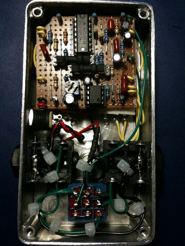
Next up was the envelope detection circuit which was a lot harder to get right (it’s probably still not right, mind you). Again I ended up with a derivative of several circuits, keeping pots for “sensitivity”, “attack” and “decay”. I also somehow made it work with a standard TL072 and not the LM1458 that the Meatball uses, but had little luck with any current limiting adjustments for the LEDs and nothing worked as I wanted it to. In the end I was inspired by the Tremulus Lune LFO and put in a trim pot set up as a voltage divider to control the LEDs off-ness. This actually worked surprisingly well and I was able to use all of the optocouplers I had at hand (VTL5C4s, NSL32s and two flavors of home-made ones).
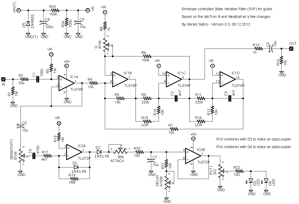
My first take on a vero layout used 2n2 caps for C2 and C3 which I found a tad bit too trebly and switched them for 4n7 ones. R9 and R11 (both 220k) sets the lower limit for the filter sweep, and R10/R12 sets the upper. I tried using 330 ohm resistors for the upper limit, but that made the sweep way too high and I changed it to 10k.
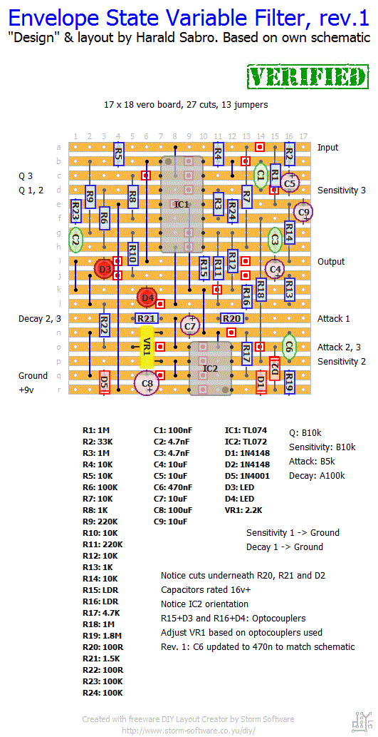
I’ve now built this successfully using cheap LDRs from smallbear (the 9203 variant) and 3mm high-brightness clear red LEDs (5mm LEDs may not fit on this layout since the optocouplers are so close) and I’m very pleased with how it sounds! Tuned the trimmer to where the LEDs were just barely off with no signal.
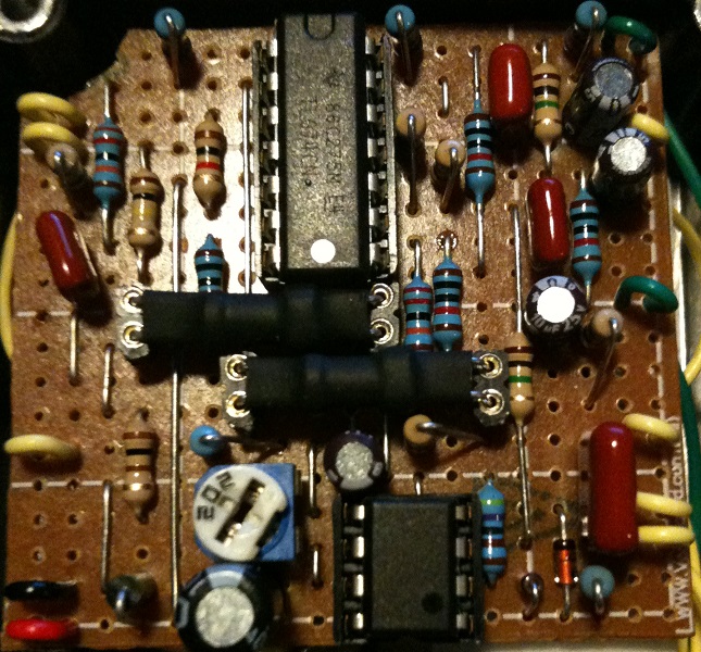
Final build images coming as soon as I get around to boxing this…
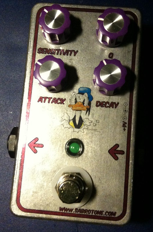
Update (08.12.2012): Build complete and I’m pretty happy with how it came out in the end. And it quacks nicely too 🙂
It was a snug fit and I had to cut off one of the corners of the board to pull it off, which annoyed me somewhat.
Also, I’ve updated the schematic. I had left an extra trimmer in there that I never ended up using.
Update (24.01.2013): Layout rev. 1: I forgot to update C6 on the layout which should be 470n (like the schematic). Fixed now.


Hi what have you used for tube over led and ldr?
Is it shrink tube?
It could certainly be done, but it might not be entirely straight forward. I do have this on my idea-list though, but no promises 😉
Would there be a way to make the auto wah switchable from auto to fixed wah?
Hey Harald, thanks for the great site and the inspiration.
I am tinkering with this effect for quite a while now and can not get it to work right. I did try to troubleshoot myself but i think you might know what i did wrong. I have to strum very hard with sensitivity maxed out to get it to work. the wahsound is very strong and the normal guitar sound seems muted(very low volume). resistors, capacitors, cuts and links i have checked and they seem to be ok. vr1 needs to be turned down all the way for the effect to work. the only differences to your design is that i used a 1n4007 diode and q7´s voltage rating is 12volts.
It would be very nice if you have a hint for me. I had like 10 working builds from vero and perf board and even a few just from schematics. never needed help, but this time i have no idea. anyway greetings from berlin Jörg Tannenberg
Thanks for the design!
I thought about making a MuTron III but that seemed like a real beast. This layout was exactly what I was looking for in an Envelope Filter. All the controls you need, a solid design, with a fairly simple and straightforward build. Just finished the case wiring, crossed my fingers and plugged it in – Immediate Quack! And It sounds GREAT! It cranked up perfectly right off the bat without even needing the trim adjusted.
Thanks again for the layout, and your website…
this site is pure rock and roll!
Cool, Masuto! Happy you like it 🙂
Built this as per layout above. Quacked right away oh yes, baby.
Aherm ☆didnt even have to adjust the multiturn trimmer☆ ahem
Thanks Sabro. Super kudos.
Hi Marcos,
I suggest trying to just get a regular LED going so you know the envelope detection section is working correctly. Assuming you’ve got socket strips where the LED/LDR components go, just insert one or both of the LEDs (try red diffused ones), play, adjust , and verify that they actually light up as you hit the strings. If you’re not getting any signal here the problem is somewhere downstream and no optocoupler is going to help.
First of all. Many thanks for your hard work to provide us this variety of circuits.
I built this little baby but, as the Dave Clark , it didnt wah. All pots works just changing the tone like a Crybaby pot
I used VTL5C1, that is pretty different from VTL5C4. Mainly in OFF and ON resistences. It is about 50M ohms against 400K ohms for OFF state and 600 ohms against 125 ohms for ON state (on a 10mA input current).
Here in Brazil is very hard to find this components, and it is expensive too. So in this way, do you know what could I change to become this circuit to work with VTL5C1
Harold, I replaced the vactrols with ldr/led pairs and sure enough, it quacked straight away. I’m not sure whether the vactrols weren’t working or were off spec, but either way its fixed now and sounds really good, I’m going to try and add the sweep switch from the mutron now, wish me luck.
Thanks for the great layouts as usual!
Dave
Thanks for the reply Harold, I’ll have a go with some leds and ldrs tonight and update you, I feel like I’m close to getting it to work so hopefully tonight will be the night!
Cheers
Dave
The problem could very well be the vactrol/led+ldr since these come in varieties with wildly differing specs. That’s not to say a vactrol won’t work, but you have to find the right one. Unfortunately I haven’t got the time or resources (money) to try out all the different ones and find out what would be a good match (the VTL5C4 seemed to work, though).
My recommendation would be to buy a few cheap ldr’s of each value from smallbear and try them out (http://www.smallbearelec.com/servlet/Detail?no=711). Takes a bit of time, but you should be able to get it working this way (I ended up using the 9200 ones).
Hi Harold,
I’ve tried this but am only getting a fixed wah sort of sound, I did use vactrols instead of leds and ldrs, do you think that could be the problem?
Cheers
Dave
That’s great to hear 🙂 Happy you like it.
Build this for a friend a couple of Weeks ago and it worked right of the bat. Great Design! I didnt have ultrabright LEDs at Hand at First and used regular 3mm red ones but swapped them after a couple of days. It was funny testing the circuit when ist was unboxed. Playing around with shadow over the ldrs was a blast. Thank you for the great Layout!
Nice design, Harald. I finished mine today and I’m quite happy with it. I made an SMT layout to facilitate a 1590A. I posted a build report at Grind Customs and BYOC if you’re interested. http://www.grindcustomsfx.com/forum/viewtopic.php?f=9&t=348
Thanks for all the cool stuff you do here.
No worry, thanks for the great job !
Sound clips is on my list. Haha, I keep saying that! Hopefully it’ll happen some day.
Hey Harald, this one looks great.
I built the Seamoon Funk Machine from Mark’s board, am waiting for the MXR Envelop filter pcb from tonepad and I may also build your’s (yeah, I love those ducky effects :-))
Any chance to have a sound clip of your’s ? 😀
Thanks
Denis
Thanks for spotting that one, Eric. I started out with a 22n but changed to 470n actually, and I forgot to update the layout.
It looks like C6 on the schematic is labeled 470n, but the layout image shows C6 as 22n. Just thought I’d point that out, I assume 22n is correct?
Very cool! Thanks for sharing, Deric 🙂
built this, love it…gigged with it and now i have to build one for my frontman…haha. thx for your efforts sir.
Hi Harald,
Could I trouble you to contact me by email? I would like your permission to use one of your images in a build document for a DIY project.
Thanks,
George
Thanks, Harald. I’m looking forward to building this one. 2 IC’s and no expensive optocouplers is awesome.
Hi chuckbuick. Thanks for noticing that trimmer. It was a remnant from a previous iteration of the circuit and I didn’t use it in my final build. I’ve updated the schematic now.
I was curious about Pot2 on the schematic. I don’t see it on the vero layout and was wondering which is correct. Thanks.
I don’t think that makes any difference, but if it helps I had mine set to a very short decay when I tuned it.
This one is, I think, more obvious than the Snow White. It sounds pretty much like the MuTron III.
Should the decay be all the way up when setting the trimpot?
Hi Harald,
well done, I look forward to build that one. A quick question, nevertheless, how would you compare your design to the White snow?
Take care
Ben