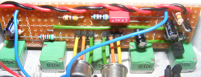
Here’s a vero layout for the Zvex Fuzz Factory with board mounted 9mm pots. This will work with the miniature Alps pots they sell at Elfa, but I’m sure the 9mm alpha pots will also fit. I’m unsure whether I’ve left adequate space between each pot, but expanding the vero with an additional strip between each pot shouldn’t be too difficult.
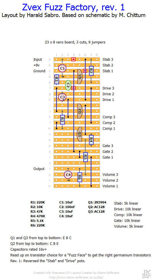
Update (04.11.2011): After having measured the pot distances on the first layout I decided it was way too narrow. Here’s a stretched out version that should fit a lot better in a Hammond 1590B.
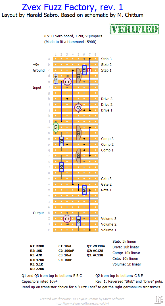
Update (10.11.2011): Restructured the layouts because both “Stab” and “Drive” pots were reverse.
Update (12.01.2012): I finished the large version tonight so that one’s verified.
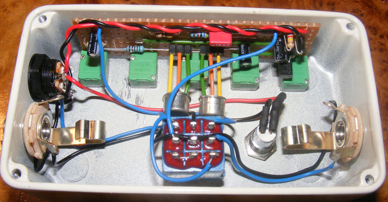
Update (10.02.2012): Got around to boxing this thing last night. This is the larger vero layout with on-board 9mm pots and I’m very happy with how it came out at the end.


small update, everything works fine now. Massive hiss when using an adapter but a wonderful sound using a battery, cheers.
this layout is wonderfull! everything works! Only problem is that when I turn up the GATE knob, my volume increases.. do you know how this could be? My volume knob works normally.
Haha, very cool! Nice work there, Jose 🙂
Hi Harald,
Just to thak you once again your layouts. This one can be modified, in order to fit the effect in a 1590A.
Just to shre it with you:
http://guitar-fx-layouts.42897.x6.nabble.com/file/n4850/fuzzfactory_mini_ok.jpg;cid=1372242372459-870
Best regards!
drsoda: elebcz on eBay sells matched pairs of (modern) AC128s for Fuzz Face and Fuzz Factory – US$4.99 each (Fuzz Factory includes a free 2N3904 transistor.) I haven’t tried mine yet, but the quoted hfe values look good (77/102 and 78/100 respectively.)
Sorry to hear that, Dan. The problem could be a number of things and I suggest you start off having a look at the debugging section.
i made this last night and when i touch the pots its makes a massive noise. needless to say it doesn’t work haha. any idea where i went wrong?
Volume -drop-? I can’t remember this producing below unity gain, but rather the opposite. Mine can be really loud.
Built this last night and it works perfectly. I did notice there is a slight volume drop. Wondering if this could be addressed?
Happy to hear it, Raul! Sleep does fix a lot of problems 😉
Hello Harald, I looked the board again after a good night of sleep and I saw that I´ve commited a stupid mistake, I inverted the “+” and the “-” on the dc jack, so, your guess about PNP or NPN transistor was kinda right! Thank you very much! Now the pedal is working fine and sounds perfectly, really good fuzz sound. This was my first experience on vero layouts,I really had to try vero after visiting your website, it´s amazing the amount of information here and the support you give for everyone. Really good job!
🙂
Hi Raul, not sure how this would occur. You’ve used PNP germanium transistors (not NPN) and oriented them correctly?
Hello Harald, I´ve built this one today (the first version) and the sound passes through the board but doesn´t distort at all, the sound comes out clean. I´ve connected the jacks directly, without any switch, just to verify if everything is working. Do you have any suggestion about what might be wrong?
Good to hear you’ve sorted it out 🙂
Hi Triton. Could be bad transistors, but more likely there’s some other small mistake somewhere; a cold solder joint, bridge, misplaced component or something similar. I suggest going over everything carefully a second time.
Finally got it working and built some other pedals too! Turns out trying to put this stuff together in the early hours is not the best idea as loads of things were in the wrong place. Cheers for the great layout and websites : D
Ok so I built the pedal exactly how the schematic is with some matched ac128s I got on eBay and it didn’t work. There’s basically no fuzz/distortion with everything turned all the way up and it won’t go into self oscillation either. Do you think it could be bad trannies?
Hi Danny, sorry to hear you’re having trouble. Did you use the smaller or the larger layout? The problem could be a lot of different things, here are a few ideas to check out off the top of my head.
Make sure you’ve got a working battery, good cables etc. If you eliminate the obvious factors you can start debugging with more confidence.
What about transistor orientations? Otherwise I’d go over everything carefully and look for missing trace cuts, jumpers or even components, cold solder joints or solder bridges. Check that all components are where they should be (maybe a resistor is off by one hole etc.).
If you’ve got an audio probe, or make one, sitting down with a schematic and listening to the signal through the circuit may also lead you to the problematic area.
Hello, I’, having lots of trouble with this one. Followed the larger layout, got all my parts together (including the AC128’s) and soldered everything in. For the 5K pots I used 4.7k ones and for the 5.1k resistor I used a 4.7k one. however when I plug my jacks in and power (haven’t added a bypass circuit yet, just got 2 jacks and a battery connector for simplicity) I don’t get any sound at all not even any fuzz or background hum. When I touch the volume pot it hums a bit but that’s it.
I have checked all the tracks for continuity and everything seems to be fine. Is it that a cap or transistor could be faulty or would this be caused by a break or short circuit on the board I haven’t found yet?
Cheers,
Sorry to hear that. Maybe an audio probe could help you find the offending connection/part a bit faster? Follow your signal through the circuit and find out where it stops.
Sorry Triton, I’m not able to supply parts. But I recommend sourcing 3PDTs from either Tayda Electronics (link on the right-hand side here) or off ebay. You should be able to find them at around $2-3, at least if you by more than one at a time.
Man, I am totally frustrated, I went through the build using Fairchild BC558’s instead of the AC128s, checked everything and all seems right (caps right direction, trans in the right way), but when I switch on, I get LED to light but not sound. I don’t hear the signal change when I move the pots, so that leads me to believe that I’ve got a break in the circuit somewhere. I’ll keep working through it and see if i can work it out. Great site btw!
Could you sell me a 3PDT switch all the places I found online have a minimum purchase of $5. Thanks.
Hi Triton. The switch isn’t soldered directly to the board, but is attached via wires only. See the off-board wiring for true-bypass in the “schematics & drawings” section.
How do you wire the switch into the board?
I’m uncertain, but I would think the 10K resistor next to it would play a much larger role in this. But I’m on thin ice here, really.
Could the 220k resistor have an effect on this? I’m pretty sure mine are 220k, but I picked them from a pile of 4000+ resistors I have and one of the bands is hard to make out.
The stab pot lowers the headroom of the effect simulating a dying battery by actually starving the effect of power, so maybe you’re running this on a battery with little power left to begin with? And I suppose this could also happen if you used a pot that’s larger than 5k.
I built this using this layout. The pedal and the LED completely turn off when the stab knob is turned all the way down. Any ideas? Thanks!
I picked it up from ebay. Shouldn’t be too hard to find, I’m sure.
where did u find strip board that big?
If I’m not mistaken the holes on a vero is 0.1″ apart. This means there’s 0.5″ (12.7mm) between each on-board pot on the smaller vero layout and 0.7″ (17.78mm) on the larger layout.
For the holes themselves it depends on the pots you use. For regular 16mm Alpha pots I use a 7mm drill bit, but for this build I used the smaller 9mm alpha pots and I can’t remember the diameter (probably 6mm or 6.5mm).
Can u tell me the measurement of the holes for the pots? Im going to build this and have the enclosure drilled because I more or less suck at drilling
Hi Dominic. I’m not sure what the product name is, but they’re 9mm Alpha pots and you can get them from http://www.smallbearelec.com
What is the name of those green Alpha pots? Thanks!
Yes. That’s exactly what it is.
Is it “Step 5?” The step where you use the drill? If I am reading it right, all it is doing is breaking the strip so it is split into multiple parts as opposed to being the complete strip (breaking the circuit).
Hi Micah. Have a look at the section called “step by step” 🙂
What is a “Cut” on the board mean? The red squares? I am new to this. I have all of the parts but do not understand what it is.
@drsoda. If you want AC128’s dude, check out “minifux1” on eBay. That’s where I get mine from & in serious amounts. He lives in Germany but ships internationally! He sells a lot of NOS gear! Milkit!
yep, i used the smaller layout – it was a bit of a squeeze, but the spacing on the inside the enclosure once assembled was ok. i’ll post build pics to my site today. thanks harald!
Great! And yes, I do believe the stab and drive pots are reversed on the layout. I’ll sort that out. Thanks for verifying 🙂 (This was the smaller layout?)
i got it working – i found a short on the board which i’ve since cleaned up, and fixed the power grounding issue. i’ve had no problems with the stab and drive pots, (however, on mine the stab and vol are the wrong way around? might be just how i oriented the board in my enclosure, no dramas otherwise. I didn’t go for germanium – ac128’s are as rare as hen’s teeth at the best of times, and near impossible to find here in australia anywhere – i substituted a pair of bc558b silicons, which seem to sound very close (not perfect) to the original, sounds great though. the build works – verified if you are happy (i can send you soundclips if you like).
Just checked the layouts again and they still seem reasonable to me. I also compared the schematic to the one from madbean and I noticed he had drawn the “Stab” and “Drive” pots the other way around which is probably the correct way. This shouldn’t impact how the circuit sounds through. Did you orient the germanium transistors correctly? The small metal tab usually indicates the emitter AFAIK.
I was under the impression this was a fuzz face sound-alike thing. What you describe seems wrong. I’ll double check the layout(s).
i’ve made this today (small version). bypass is quiet (and plays clean guitar), but when the circuit is on it is noisy and self generating, with the effected guitar mixed into it. is the sound supposed to be discrete (only when guitar is playing) or have i made a bad ground? i’ve tested the vero lines and soldering, all seems in order..
Thanks, and you’re welcome 🙂
you are a legend, harald. awesome stuff!