Did a vero layout for the MXR Phase 90 effect yesterday. Looked over it once after I was done, but can’t yet guarantee that it works. Will have to make it one day soon.

Update (12.09.2010): Went over the layout a second time and corrected a small error; I had the output on the wrong side of the output cap, and consequently had to add another column to make room for the correct output. I’m now confident enough about the layout that I’ll start working on a vero board and source the necessary parts.
Update (14.07.2011): Finished this one the other day and as with the Omnidrive I’m not really that happy about the outcome visually, but unlike the Omnidrive I think this one sounds great!
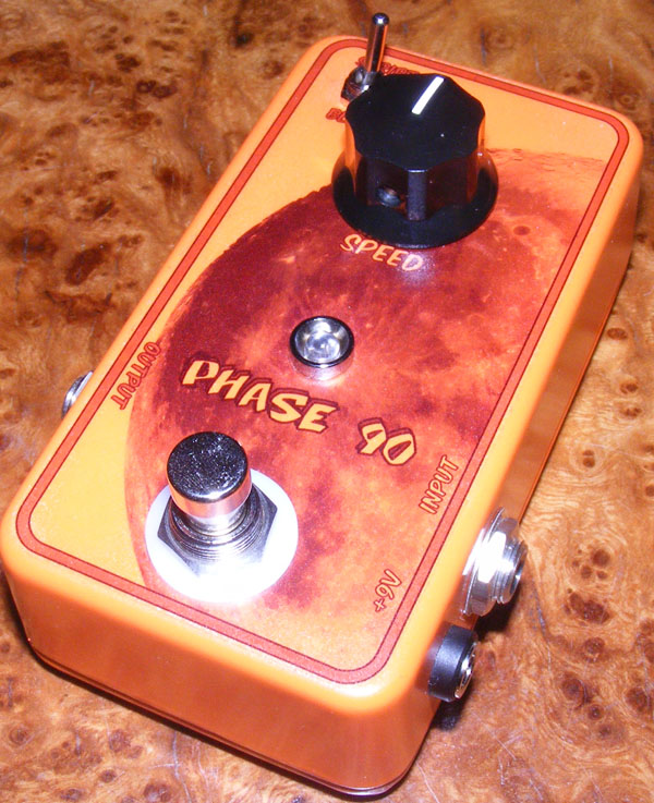

This was a tight fit in a 1590B enclosure and putting it together was great fun. It was only after having soldered the last wire I realized I forgot to take a picture of the board itself, and I didn’t want to take it apart again, so no board shot of this one, sorry.
Update (20.10.2011): Fixed dead picture links.


I cannot find a 15uF cap. Will a 10uF and 4.7uF cap in parallel help? It gives 14.7uF.
Thanks! I’ll Let you know
I don’t know, but it’s worth a try!
– Remove R22 and R25.
– Try a linear potmeter of, maybe, 250k.
– Lug #1 goes to where “Script SW 1” is on the board.
– Lug #2 goes at Q5 base, (j,25 perhaps).
– Lug #3 goes to where we removed R22, at (k,20).
Hi harald. Is it possible put a blend pot? Blend i mean clean or processing signal. Thanks
I might be mixing them up, but one side (I think it’s the block side) is somewhat more distinct/intense, but it is a subtle change. If you look at e.g. the tonepad schematic you can see that the switch essentially makes or breaks a local feedback loop in the phaser section, and this accounts for the variation in sound.
Hello again!
Quick question (I think!): what’s the difference between the script and the block modes?
Miguel, either will probably do just fine, but I presume it may change the LFO range somewhat. As an alternative you could parallel a 10u and a 4u7 to get the required capacitance.
Hey!
I don’t have 15uF capacitor for C9, the closest value I have is 10uF and 22uF. Can I use any of those two?
Hi Austin,
I haven’t tried, but I wouldn’t bet on it. Whatever FETs you end up using, remember to use a matched quad or you will most likely have little or no phasing anyway. R.G. Keen has some excellent articles on matching FETs over at http://www.geofex.com
I bought a bag of 200x 2N5952 and measured them all to get a few matching sets. Might be easier to do in the long run, but that’s my opinion.
Will J201s work in place of the 2n5952s?
From looking at the schematic there’s no gain stage that can quickly and easily be upped, but what you could do is add an extra opamp or transistor stage at the end with moderate/adjustable gain. Another possibility is to experiment with the gain in the phaser stages (like slightly increasing R3, R8, R13 and R20), but that might also end up affecting the overall sound.
Hello I built two of these and sounds amazing, very good with mpf102´s instead the 2N5952, the issue is that with the pedal in effect mode the overall volume drops a little, how can I correct it? some ideas?
Thanks for this amazing layout!
Happy to hear you’ve got it working and sounding good! The signal clipping could be several things, but it basically comes down to you giving the pedal a larger amplitude signal than it can reasonably handle. Are you using a battery that’s about to go (lowering the effect’s headroom)? Are you using active pickups (typically outputs much more signal than passive ones)? Does your overdrive come with both gain and volume controls, in which case it could be helpful to use the volume to limit the signal fed to the phaser?
Just a few things off the top of my head. Hope you solve it.
Hello again Harald,
I just managed to build the phase 90 again with matched fets. Now it sounds awesome! 😀
But the thing is, it distorts really badly when I hit the strings harder or I use an overdrive before it. I desoldered the components from the first build and resoldered them into a new board, so maybe something was damaged. Any idea how i can find it ?
Thank you very much for the quality layouts and the help.
Yes, you can probably not hear the difference using 47nF.
Can I use 47nF caps instead of 50nf? :/
It’s kind of an emergency question :S
Periklis, I don’t know where to begin to be honest. Could you provide IC and transistor voltages?
Hi thank you very much for the layouts! I just build the Mu Tron III and sounds amazing. And this is my second build. But i would apprieciate a little help.
Every time I turn it on it sounds like a velcro fuzz thing… and i also get some weird unstable voltage readings one the bottom left transistor. Pliz help. Tnanks 🙂
If you don’t match them you may have a reduced phase effect (or no phasing at all). So you probably want as good a match has you can get.
hi harald
how close matched the fets should be ?
tnx
dtaboso,
Ideally it should be an anti-log / reverse audio / C taper pot.
pot 500k is lin or log?
thanks you
Thanks Harold. I figured it out last night. I actually prefer the script mode anyways so I got rid of the toggle and added a “depth” control and a “quasi volume” control. Thanks!
Try keeping the wires as short as possible and out of the way of the other connections. I had the same problem with my first build and that’s how I solved it. Hope it helps.
I just built this and the script mode works perfectly but when I switch to the block mode I get a very loud highpitched squeal/siren sound. Any clue what could be causing this? Thanks!
I made one with a depth pot in stead of R17. Nice mod. Thanks for this layout Harald!
Good question. I’m not sure to be honest, but there’s bound to be a few threads about transistors in the phase 90 if you search the forums.
What would be a good substitute for the 2N5952?
This one was great fun to build and I really like the outcome.
Thanks Harald!
//Stefan
Yes, you need to match the transistors to get a solid phase effect.
Harald
So as per Rolf’s comment, is it important for the 2N5459 to be matched?
Tim
Yes it works, you can adjust VR1 very easy, i have build it yesterday 271011(dutch). It was very easy to buy a matched set 2N5259 in Holland at Newtone online.
Regards Rolf.
Have a look at Tonepad. They have the schematic (and you can order an excellent PCB if you’d rather not do your own vero board).
You have a scheme whereby you build it?
I’m not entirely sure what you mean, Dreight? Is it the wiring you’re referring to?
Hi, can you please make more detailed plan?….I´d like to know more esspecially about (1st and 2nd) switch connection and rate control connection. Please contact me on e-mail. THX 😉
Yes. I’ve successfully built this myself.
Hi I want to ask one question: Does it work? Because I would like to construct it. 😀