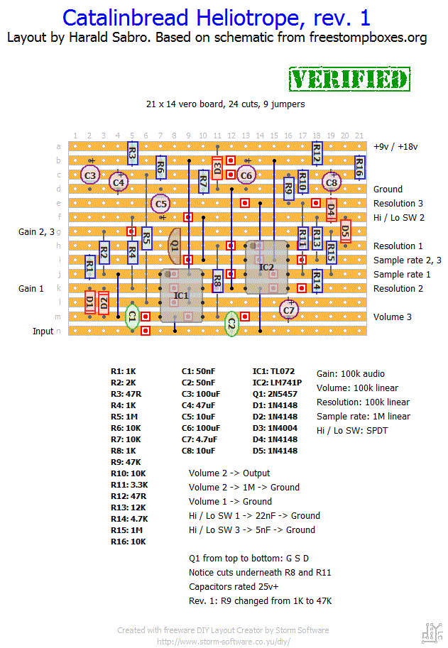
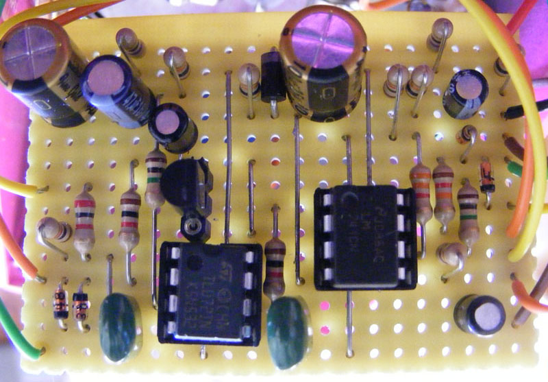
Did a layout for this weird effect the other day. From the demonstration videos found on youtube this sounds like a ring modulator with some added twists. Not everyone’s cup of tea, but at least here’s a vero layout for it!

Update (20.07.2010): Populated a vero board according to my layout last night and I can now confirm it. What an obnoxious effect… 😉 Note: I had missed one label, “Volume 1 -> Ground”, which has now been corrected.
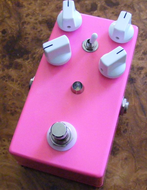
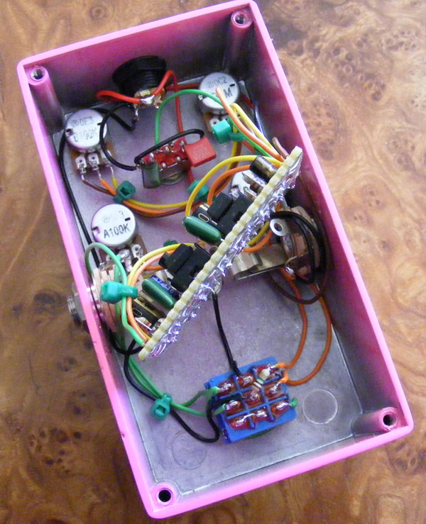
Update (08.11.2010): The Catalinbread Heliotrope build is now complete (has been for a few weeks, but I didn’t pull out the camera until now). Hot pink to match it’s sonic qualities!
Update (15.02.2011): Updated the value of R9 after the original schematic was revised.
Update (20.10.2011): Fixed dead picture links.


Thanks for the layout!
Just checked it out and it seems to work. I say ‘seems’ because it’s hard to tell from the videos exactly what it does and this is one nasty ass noise machine…I LOVE IT!
So whether this is dead on who cares it sure sounds great!
Thanks again
Does anyone have a good picture of the inside of the heliotrope? I just want to see it so I can decide if there’s enough space inside the box that catalinbread puts it in for making a mod. thanks.
I tried using shielded wire from each jack and from the input/output and I still get a persistent whine which changes pitch depending on a knob sweep, it isn’t present at full volume or low volume, but the middle sweep is pretty annoying, like tinnitus. Has anyone found this/solved this issue?
I love this effect and if I can’t fix my build I would absolutely buy a real one.
I’m not familiar with that wiring and the layout it refers to, so I’ll leave this one up to Jimmie.
Hi, this will be my first “bigger” build and I have one question regarding Jimmie’s offboard wiring. Connecting the lower lug of the switch to pin 2 of IC2 means connecting the lug to “i-13” on the vero, is this correct? Thanks in advance! Keep up the great work here!
Sounds great, Jimmie 🙂
the mystery is solved! i got rid of the whine that occurs in bypass.
i made a modified version of IvMarks offboard wiring that you will need:
https://dl.dropbox.com/u/2828668/reaperpedals/the%20pale%20horse/offboard_wiring_heliotrope.jpg
so basically it’s splitting the ground up and just take the lower lug to pin 2 at the LM741 IC to have it’s input grounded while the effect is turned of.
this way you can still have the LED. just tried it and it works flawlessly and no whine in bypass whatsoever.
also, heres a demo of my build:
http://www.youtube.com/watch?v=cj-fRvIOC2k&feature=youtu.be
Congratulations on first vero 🙂 That whine is due to this being a high-gain effect. This means you have to be careful when you wire everything up; keep inputs and outputs away from each other, keep wires short and to the point, try to minimize wires running in parallel (cross them at 90 degree angles if possible).
Hi Harald
I built this yesterday. My first build based on a vero from you. =)
It works great, but I also get that constant whining sound no matter what.
Anyway, keep up the good work! Greetings from Sweden
/ Freppo
That would probably be feedback oscillation caused by some part of the signal leaking into another part of the circuit where it’s not meant to be. This effect is high gain and should be treated with care when it comes to wiring etc. Keep input and output physically separate as much as possible. Keep wiring as short as possible. Be careful clustering different wires together and if wires need to cross they should ideally do so at 90 degree angles.
If you browse around on the effects forums I’m sure you’ll be able to find a few topics discussing the perils of boxing high gain circuits.
I get the same constant whine (very annoying).
What could that be?
Even used isolated cables for inputs and outputs!
Any help would be appreciated.
Thanks
Anyone else get a constant whine (pitched) when not playing?
I love the effect, sweet ring mod and crunchy 8 bit sounds from this baby!
Sounds like a fun mod. Maybe you can add a switch to toggle between the two values? Happy to hear you found out what was wrong 🙂
Solved it. I accidentally placed a 4,7M resistor in place of a 4,7k for R14. No wonder the pot did nothing, the wiper was always way beyond the pot’s capacity. However I must say that with the 4,7M i got a nice lo-fi tremolo-type effect where the sample rate regulated the speed. Worth checking out, and even might make it a build in the future.
Cheers!
I spoke without checking, I memorized the Resolution pot as 1M but actually it’s 100K. I’ve successfully connected the 1M sample Rate pot though, and followed everything on the diagram but the Resolution pot does nothing whatsoever. Might be a faulty pot, but I’m still waiting for a new one to arrive so I had to ask if anything here might be the problem. I’ll go quadruple check everything and get back with the results.
Cheers.
By 1M pot you mean the “Sample Rate” pot I assume. Yes, this is the case in my layout as well. You connect lugs 2 and 3 together and run one common wire from either lug to the board. And, not to confuse you further, technically you can also get away with just connecting a wire to lug #2 and leaving lug #3 completely out.
As for the Resolution pot I can’t really help you there other than to assure you the layout has been verified as working several times. I’d look for a short somewhere. Double check your wires, and do try a different pot if necessary.
Cheers, just finished this one up, everything works fine but I get no reaction from the Res pot. I’ve seen a schematic where lugs 2 and 3 of the 1M pot are directly connected together, so this confuses me. Any ideas?
Hi again Harald
still not working 🙁 have triple checked the board, and also replaced the 2N5457 / TL072 / LM741. LED works, pedal bypass works… but that’s all that works. Is there any chance you could add a simple drawing showing exactly how you have yours wiring – I would very much appreciate it. Would really love to get this pedal working.
You could do that, but since there’s limited space on the board I suggest you connect 21D to lug #1 of the Volume pot, then run another connection from lug #1 to a DC/signal jack.
Looking at your new schematic, can I confirm the wire from Vol Lug 1 goes to 21D on the circuit board, then an additional wire soldered to 21D ground to either Jack or DC ground.
Cheers Harald
was a little confusing, shall let you know how it goes.
Now that I look at it I realize you’ve found a mistake in the layout. I’ve forgotten to specify you have to wire “Volume” lug #1 to ground.
You should connect both the “Ground” label at 21D and lug #1 of the “Volume” pot to ground. Either of the jack sleeves or the DC jack pin will do since they all connect to ground.
(And I’ll update the layout as soon as I get the chance).
Many thanks for you support Harald 🙂
I feel am getting this now, strange config for me,
have been building mostly Fuzz. So the ground at point (21/D)on the circuit goes to ground via one of the black round points, as apposed to Vol Lug 1 to the circuit… is that correct.
Have another look at the true bypass wiring illustration. Apart from the wire connecting the LED cathode to lug #4 on the 3PDT, all the black wiring represents ground. Any of these points can be used when connecting anything to ground.
According to the layout you need to draw a wire between lug #2 on the “Volume” pot to the location on the true bypass illustration labeled “circuit output”. You also need to draw a wire between lug #1 on the “Volume” pot to any round point. Next you need to add a 1M resistor between lug #2 on the “Volume” pot to any ground point (this is most conveniently solved by placing it either between lug #5 and #7 on the 3PDT or between lug #1 and #2 on the “Volume” pot. Lastly you need to wire the board label “Hi/Lo SW 2” to the center lug (#2) on an SPDT on-on switch, solder one leg of a 22n capacitor to either outside lug on the same switch, solder one leg of a 5n capacitor to the other outside lug on the switch, then connect the two remaining capacitor legs to any ground point.
You can make out some of the wiring in this picture (notice I chose to solder the 1M resistor to lug #5 and #7 on the 3PDT).
Harald
will try that, have been meaning to make an audio probe. Also can you tell me – I have linked a wire from Lug 1 on the VOL pot to ground on the board. Do I also need to take a wire from that ground point on the board to the output jack output? Also I have added a 1M resistor to lug 2 on the VOL pot to the output point on the 3PDT – is that correct?
maybe you could take some more shots of how you wired it all up – would really help 🙂
You’ll find an overview of how I usually do off-board wiring in the “Schematics & drawings” section. Here’s direct links: True bypass wiring, switch numbering and pot numbering.
Otherwise I recommend the excellent debugging guide over at http://www.geofex.com for general debugging. If that doesn’t help make yourself an audio probe, inject an audio signal and follow the signal path through the layout referencing the schematic found in this thread. Hopefully that’ll help you find out where the problem is.
Hi Harald
have tried building the Heliotrope, and with no success… Sadly am getting no sound. LED works, 3PDT also works in bypass. Could you possibly add a wiring diagram from circuit board to pots/in/outs and especially how you wired to your 3PDT foots switch. The sketch would do Would also be a major help on this unusual and interesting build.
Can’t say for sure as I haven’t yet gotten around to boxing this thing, and I’m not an expert in these things by any stretch of the imagination, but I know you can eliminate some oscillation issues by keeping wire lengths to a minimum and try to separate the input and output wires as much as possible.
Finally got this thing working… sounds awesome!! Theres just one thing I’m not sure about. When I bypass the effect I still here the oscillator sound, is this just the nature of the circuit, or is there some way to fix this?
oh, ok I see… I just can’t seem to get power to the one I made, and I’m trying to figure it out… The switch bypasses the pedal, but when it’s on, no sound or led light. So I don’t know if it’s a wiring thing or something w/ the board. Any tips on problems like this? oh, thanks btw, for answering my questions, really appreciate it.
You had me looking up the layout, and it hit me that the easiest way would be to wire the volume pot lug #2 to output as usual and just place the 1M resistor between lugs #1 and #2 on the volume pot (lug #1 should be going to ground as per the layout).
Ok, in regards to that heliotrope problem… so I went from the lug 2 of volume pot to a 1m resistor to output lug on the 3pdt switch, is this what you meant on that last comment? or are you saying ground the 1m somewhere then have another wire coming out of lug two on the pot to the output lug on the 3pdt?