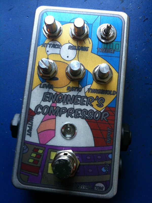
Another compressor, this one by Merlin/ValveWizard. I chose to incorporate all the suggested mods on this layout. Let me know if you beat me to it building this one.
Update (06.08.2012): This might just be my favorite compressor thus far!
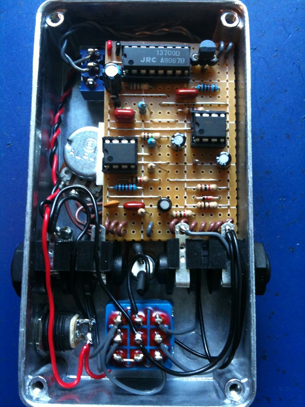
I was lucky when boxing this. Had I moved the jacks just a mm more in the wrong direction the board wouldn’t have fit the way it does now. But then again if I hadn’t added two extra columns to the vero for the wires it could have probably gone in vertically just fine. Anyway, really cool effect 🙂
Update (14.08.2012): Some of you have asked how to modify this to opt out of all the extra controls and have just the “ratio” and “level” ones. Here’s how to do t with the current layout:
1. Ignore the “attack” labels and instead add a 100 ohm resistor between them; a good place would be between pads (N2) and (O2).
2. Ignore the “release” labels and instead add a 1M resistor between them; for instance between pads (J7) and (L7).
3. Ignore the “threshold” labels. Add a 1M resistor in place of “threshold 1” and “threshold 2”; a good place would be pads (I9) and (M9), and add a wire link between “threshold 2” and “threshold 3”, probably best achieved by running a wire between pads (C1) and (M1).
4. Ignore the “treble” switch labels and leave these disconnected (you can also omit C3 and R4 as these are only used for the treble switch mod, but these can be left in with no detriment to the sound).


Well. I just built this and it works!! Only … er … entirely not as intended. I seem to have accidentally created a distortion pedal instead of a compressor. So far I’ve only done a quick visual check so far and everything seems all present and correct sadly. Just wondering, before I go all deep dive and loose a day, if anyone might have a hunch as to what I might have done wrong. ?
Will update as I test.
Hey, vefa. I experienced a problem just like that. It comes, when part of the envelope detector is not working, but not all of it. In my case it was the release pot that had a bad connection.
Hi. I gave it a try and completed the circuit without any alterations to the schematic and materials. Except for the potentiometers all of which are linear. I was not able to find log pots. Double checked all the jumpers and connections. I plug the circuit and sound seems to be bypassed, with less volume. Whenever I decrease the Ratio all the way down, the sound turns back to its original volume suddenly, not gradually. None of the pots seem to affect the sound except for the ratio and level pots. Seems like I made a mistake but am not experienced enough to find out what. I’d check the voltages but don’t know where to measure and what to expect. I really appreciate any help.
Nice, ed!
Third build from your layouts, now completed. I had some auto oscillation troubles and it’s only after 5 checks of my board that i discovered your topic about squealing/whining/oscillating. I did again all the wiring of the pedal and i added a 12K resistor to release 1 and a 10K to attack 1 and it’s now working great.
Thanks again for the good job, great website !
Thanks Harald. I have my stripboard prepped and components layed out. Working on the template for the enclosure. Hope to start soon!
If I had to choose I’d probably get rid of the attack and release pots and replace them with resistors of 100ohm and 1M respectively.
Which of the knobs is least useful in your experience? In fact, if you had to rate them in order of importance (being able to change values through a pot), what would your list be?
Thanks Harald!!
Hi Phillip,
You’re right about pin #4, the negative side of C6 should go there. And if you notice the jumper next to it you’ll know what side of C5 should be the negative too; you’re quite right.
I’m using a tant cap for C5 and C6 (because that’s what I’ve got;) and I was wondering about the polarity. I was assuming that Pin4 of IC2 would feed into the negative side of C5. Is this correct? If it is correct, would C6 be oriented the same as well?
That’s great news, petevig! I hope you like the result, I do 🙂
You’re of course right about the switch. Where’s my head? 🙂
I knew it was me, it always is. No more building after 1AM. LOL I went back to square one and counted out the cuts, right quantity, but one in wrong location. MY cut at 15j should have been YOUR layout cut at 15k, the missed cut puts switch connecting everything on one side to IC2-8. Boy do I feel dumb. As Always, great job, great layout and heartfelt thanks for all you and others like you do.
Understood, but isn’t that the point, that when the two wires connect, you get treble boost? I also noticed a BS170 in the circuit and was curious why that was omitted. I do find that I can remove the 2N5087 (BC327) from its socket and the circuit still works. Thanks for your reply, I will continue plugging away until I find it. Pete
You’re looking at the +4.5v bias voltage. It might seem strange at first, but if you look up the schematic again you’ll notice the +4.5v label quite a few places, and all these components actually do connect (the schematic is just written this way to make it less cluttered and more readable).
Now, why you’d have dead silence when toggling the switch I’m not sure. Could there be a short somewhere, maybe between the lugs on the switch itself?
Harald,
Far be it from me to question the layout, but I have completed my build, and everything works EXCEPT for the Treble Switch. I have been over and over and over the board and simply cannot resolve. All the knobs work as designed. When I flip SW1, the circuit goes dead, completely. I have looked at the schematic and can see where the treble mod is added, which is where my question comes from. in your layout, SW1 row N (14) connects to R4(10k) then C3(4n7) then R11(1k), then IC2-6,. OR the jumper at col 13, then IC3-4, and to IC3-1 thru R12,, or to Threshold 1, or to the jumper at col 9, then to IC1-6. I am a total idiot with electronics, schematics and layouts, but something does not seem right. Thoughts…please. Thanks in advance.
Excelent. I did it correctly then. Just based on a guess. Thanks for the help.
Hi Stephen,
negative side of the electrolytic capacitors goes to the “h” and “n” tracks (in other words, both caps oriented with negative towards the top).
I have a quick question. The capacitors I have for C5 and C6 have a positive and negative. Do you know how these should be oriented?
Hi Palo, I don’t know the frequency response, but it’s quite possible it will work for bass too.
You can read about the effect from the designer here: http://www.valvewizard.co.uk/engineersthumb.html
Hello, I’m from Argentina.
¿It works well with bass guitar? I mean, ¿It cuts low frequencies? ¿Do you know the frequency response of the pedal?
¡Thanks!
—
Palo
Alright. Happy to hear that then 🙂
Thanks for the explanation Harald! Maybe I didn’t test this properly before, but with the threshold all CW the difference is obvious between ratio all CW or CCW. Though I still change the level almost a quarter turn for quiet notes to sound about the same. Since I also checked every component and connection twice, I’m thinking it probably works just fine 😛
Hi Bart. Here’s how mine works:
This is with attack and release at noon.
– With threshold at noon the ratio control starts compressing at about noon as well.
– With threshold all the way CCW the ratio never compresses much but instead acts as a gain control.
– With threshold all the way CW the ration does full on compression without changing the volume pretty much through it’s entire sweep.
Could it be that you’ve wired the threshold wrong or something related to that, something that prevents your threshold control from going anywhere but fully CCW?
Hope you can fix it 🙂
Hey Harald. It’s like I said, everything seems to work OK, except the ratio changes overall volume, no matter if I play really quiet or really loud.
Sooo… I don’t mean to nag, but if you could check with your pedal, that would be cool! 😀 It’s 99% a mistake by me, but I need some extra motivation to debug this I guess. It doesn’t help that there are no demos, not of this awesome 5-knob version anyway..
Yes, I would think the ratio should only affect signal above threshold, and should not work as a volume control. I’ll have to check how mine sounds, but assuming there’s a problem I’m not sure where you should start debugging. Could this occur if you feed it a signal that’s much too large or small?
As for the release (and attack) pots they probably should have had a small resistance in series to prevent you from removing the resistance altogether.
Hey. Thanks very much for the layout Harald! I built this with all the controls but there is one “problem”:
The ratio control only changes the overall volume some for me? When I compensate with the level control the sound seems (to my ears) exactly the same. Is this normal? The ratio is supposed to affect only signal above threshold, right?
Also, but I think this is normal, the pedal gets quite noisy with the release all the way down?
Doesn’t hurt to give it a try, but I can’t tell you whether it’ll work or not.
Hi Harald, in place of the treble switch if I want a tone knob, can I replace R4 for say 10KB pot and short treble switch 1 and 2 output? will it act as a tone knob then?
Cool. Just wanted to make sure – next on the list. Haven’t built a compressor in a while. Jazzed about getting this one together.
Thanks
Good guess, but no. I do mean 100 ohms for the attack. 100 ohm is default, and increase to taste (that’s where the pot comes in), whereas the two other pots are “decrease to taste”.
In the mod section for fewer knobs, you say, “Ignore the “attack” labels and instead add a 100 ohm resistor between them. Did you mean 100k? I ask because all the others mirror the value of the original potentiometers. Should this one use a 100k resistor since the attack pot was a 100k?
Built it, the best compressor thus far. I built it 2 with pots, but then I put them all back because they are useful to tweak the compression to taste.
Another great layout Harald!
Costantino
Built this one last night, fired up first try 🙂 what an amazing compressor (best DIY one I have built so far), thanks for the layout!
I’ll update my post with instructions on how to build this with just the two default controls. Hang on.
I’d really love to have a compressor this good but with fewer knobs. Could you please give some instruction on how to build the original two-knob version?
You’ll find the whole project (including schematic) on Valve Wizard’s own website. I’ve added a link on the right-hand side.
Cool!!
Great with a compressor with both attack and release knobs!
Do you have the schematic that this layout is based on? I want to try to modify it to enable side chaining from a separate input!
K
Compressor with blend is noted. The philosopher has one by the way.
It’s not unusual for a compressor having only unity gain so I don’t think that’s wrong on your build.
ooohh…. this looks fun. I was really hoping for a comp with a blend knob on it, but this has literally every other feature I could want. Harald, I know you’re a compressor fan… can we get one with a blend knob incorporated? The wampler ego and the barber tone press are two that I know of that have the blend knob. I’d also like to tackle the orange squeezer with the attack knob- GGG has a schematic for that.
If noone has tried this by the time I get my parts ordered and 2 other projects in front of line, I’ll be the guinea pig on this one!
Built! And it sounds great! I haven’t boxed it yet, but everything seems to work. One question, though: It seems to stop at unity gain, volumewise. Is this normal? No boost?
I’m going to try it soon as I have the time, just busy relocating these days, but I guess that was quite obvious 🙂
I’m gonna build this soon maybe within a week or 2. Was going to build the pcb version but since Harald did this vero with all the controls ill give it a go and try to verify.
anyone build this? I’m a compressor nut like you harald and have been waiting to find the money compressor- I’d like to try the diamond comp, but man that’s an intense build!! I’d screw it up for sure. I’ve really been wanting a comp with ratio/attack/release knobs, but also a blend knob too- i’d try to verify this if you knew how I could add a blend (mix) knob to it, or if you knew of a videod demo or review?
Thanks for everything you do! we love you man!