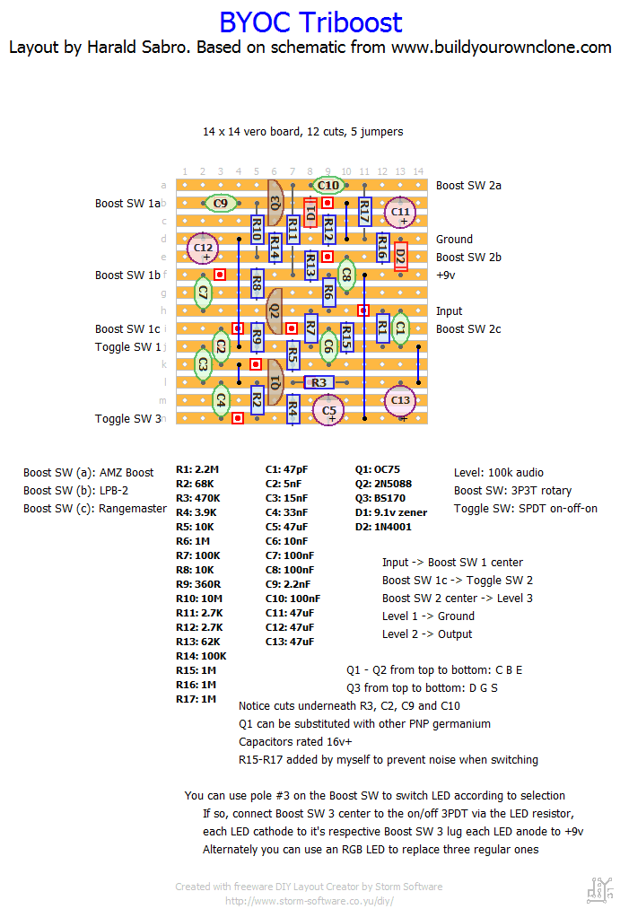
Three boosts in one box. You choose which one to use by means of a rotary switch. Looks like it’s the AMZ Mosfet Boost, the LPB-2 and the Dallas Rangemaster.
I was tempted to add a separate gain/volume control to each boost and it would have also been cool to have some sort of stomp toggle switching (maybe CMOS?) between each, but I decided not to complicate things and just leave it as is. I did however add 1M resistors to the output switching as I’m fairly sure those capacitors hanging there could produce some noise when operating the rotary switch. Feel free to leave them out if I’m wrong, though (R15-R17).
I did add some textual description on how to wire the indicator LED(s), but by now I’m quite comfortable with most wiring and I can’t really remember how I used to have to wrap my head around this stuff. If you’re just getting into this hobby and get a headache trying to decipher what I mean I’m really sorry. Drop me a line and I’ll consider adding some more illustrations.


Thanks, Strassercaster!
I am really happy with this one its fantastic. I picked a PNP low leakage .08 with 84 hfe transistor . With the 3.9k bias transistor it was 7.1v i would say thats about perfect as 6.6v-7.2 is the goal.When I use a trimmer for a rangemaster i usually like it at 7.0v-7.2 this way if the weather or temp is hot the voltage drops a tad and your still in the zone.
The rotary switch seemed a little confusing at first. You take the input from the footswitch to center lug one and the input from the board from center lug one as well. Real rangemasters have a 10k pot but the 100k pot didnt seem to change it much. I may try a switch to go to a 0k just for the rangemaster part. I really like Rangemasters. I did change the caps for that part. I used an 8.2n for C2 as the 5nf was to shrill with my gear. I then used 10n for c3 and kept the c4 the same The mosfet is A the silicon is B and the range master is C. 1A would be the in for the mosfet 1B is the in for the Silicon 2n5088 and 1C is the in for the range master .2A is out for mosfet 2B is out for the silicon and 2C is out for the rangemaster so center lug 2 is out off the rotary to the footswitch out .
I also used A TRICOLOR LED with common positive like he says you wire rotary center 3 from your normal footswitch for led position and hot wire the positive with a limiting resistor for the tricolor led from the power jack and or battery.Then just put the 3 different colors on 3a 3b and 3c
Good to see you back Harold I am looking forward to more of your Fantastic layouts This was the 11th different layout I have done off your site I want to say thanks again I started the ADA Flanger today and have it built . Later today I will calibrate it man what a job
Verified
I have an actual BYOC triboost. I would be happy to try to answer any questions.
Ah yes, the 100k trimmer. I skipped that one.
It’s for adjusting the bias voltage on the AMZ Mosfet boost part of the circuit, but I decided to save a bit of space and use the recommended value from the original circuit (62k).
…great! Thanks a lot! I hope I’ll be able to verify it in the next months, as soon as I can find a 3P3T rotary switch (which seems to be unknown to the European suppliers, uh…).
Just one note… the BYOC schematic reports a 100k trimpot; in the schematic it seems to be part of an alternative way to build the circuit which I can’t understand.
What’s your opinion about that, Harald?
That’s what it says. It’s set up the other way around, though, so it’ll still sit with the collector at the lower voltage potential (ground) compared to the emitter at +9v. I haven’t tried it myself, so I can’t tell you whether this will work or not, but it’s probably correct.
if this uses a PNP germanium shouldnt it be -9v???