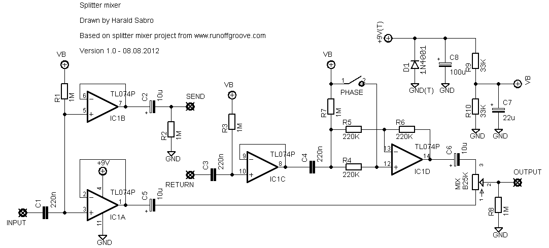
This is a utility pedal I’ve been planning to do for a long time. I based this heavily on the “splitter blend” project off runoffgroove, but instead of splitting into two send/return paths I wanted only one loop and the ability to mix this with the dry signal. Since this left me with a spare opamp stage I decided to use this in place of the source-follower in the phase switch section. Thus the schematic ended up looking like this.
And the vero layout to go with it.
I plan on sticking two or three of these in an enclosure with separate 3PDTs and LEDs for each loop. Let me know if you beat me to it and build this, and whether you made it work or not.
Update (16.08.2012): Built this last night and it works. I’ve also corrected a minor mistake on the layout (IC1 said TL072 and not TL074).


Am I understanding correctly that 220n capacitors here are coupling capacitors and I can increase their value to 470n without significant change in the sound? Thanks
Hi Harold.
Great layout! Worked first time but had major shotgun style popping.
I added 10M pulldown resistor on the input to ground and 1M on the output to ground which ‘solved’ it, but it would still pop if i tried to use it right away. Like id have to leave it plugged in but not engaged for about 10 seconds otherwise it would still pop.
I think ive solved it properly now using an alternate footswitch wiring where the input and output of the board are both grounded on bypass. On a 3pdt it goes: 1&6->Board In
2->Jack In
3&7->Jack Out
4->LED-
5&9->Ground
8->Board Out
Hi Harald. You mentioned putting several of these into one box. I’ve been trying to find any information on the interwebs on how to do this and keep each circuit in parallel. I’d like to put this one and the ROG two channel splitter/blender into one enclosure for a 3 channel blender with control for a dry signal, but if I do this the conventional way, wouldn’t I just be putting these parallel loops in series with eachother? Thanks for any insight you might have.
Greetings,
i was just wondering if i could install this circuit inside a distortion pedal with trim pot so i can make it have blend clean signal.
Sould i change any values to make it bass friendly maybe the input capacitor?
Hi Raphael,
The volume drop is natural, and part of how the mixing works. The pot simultaneously lowers the volume of one side and raises the volume of the other side as you turn it back and forth, the idea being that you should find the ideal spot with your desired ratio of wet and dry signal. If you need a volume increase the easiest and most flexible way to get it could be to string a small boost effect into the chain.
Hi Harald, I stumbled across your site while looking for a project like this. I built this pedal today and I love it! As a bass player, I’m excited to use this thing to try out some more distortion options. Quick question– I’m noticing volume drop as I turn up the mix control. Would an audio taper pot give a more even blend? Thanks!
do not mind my question it works perfectly I put wrong caps values
thanks
Good to hear, luis 🙂
Thanks Harald, built this and works very well with my overdrive pedals
Tnx for the answer Harald I followed the project and mounted R1 and R8…
No cold solders i think, I was very careful…
I’ll try the Analogman alternative wiring…
P.s. anyone with the some problem? Or im the only one?
Hi Poorboy. I’m not an expert on popping by any stretch, so I have very little in the way of advice. But have you eliminated the obvious, like one of the 1M resistors missing, or having a cold solder joint, that kind of thing?
Hi Harald.
I’ve build this project and works very fine, no signal lost… great!
But i’ve a popping problem when i switch on the pedal..
Im using Tonepad wiring n. 5…
Can you help me?
Will,
wish I could give you a good answer, but I don’t know enough about pickups to qualify. My guess is it’ll work fine, though.
Would this be appropriate as an onboard mixer for isolating/blending 2 pickups?
Hi, any chance you could do a layout for the stock Splitter-Blend? I would do it myself but I’d rather use one from someone who knows what they’re doing. 🙂
Don’t know any schematic, but I’m guessing this should be pretty straight forward to make. Interesting idea.
Hey Harald, thanks for this. Built it a while ago and it’s pretty great. You can do cool stuff with it, or sometimes I just use it as true bypass loop.
I was thinking of building a new pedal with two loops and 3 pots for dry/loop1/loop2 volume. Do you know of any schematic/pedal that does this?
Happy you like it. I do to!
You would need to host your picture somewhere else, but you can then post a URL here for all of us to see.
Built this and it’s perfect. Great blend range. No tone suck. Full dry to wet. Thanks so much. Any way to post a pic here?
You could probably tell me! I haven’t got a tight grasp of the theory yet and I stuck with the same values as the ROG variant I based this on.
Hi, Harald! Great page with nice stuff you got here! Congrats!
Just a little doubt: why 1M for R2? That’s such an impedance for an output… Wouldn’t it be convenient to use a lower value?
Thanks in advance!
Good and bad news, Marko. The good news is I built this now and it works great, which means the layout is most likely correct. The bad news is of course that you have to do a bit of debugging.
Please Harald don’t appologise man 🙂 THank you so much for everything that you are doing.
I will be anxious to hear whether or not your build works as expected. It’s a fairly simple build, so it wouldn’t take much of your time…Cheers friend.
Sorry you’re having issues with this one, Marko. I’m going to build this myself as soon as possible, after which I’ll probably be able to give you some better answers.
Oh, now it is a nightmare to follow all that stuff..anyways, it is not working, I wonder what could be wrong, it has to be some mixup with the opamp pins…I checked my vero a and there is nothing connected that it should not be, or anything not connected. What a bad luck with this build.
I didn’t strictly adhere to the schematic when it came to opamp sections. I swapped pins 1-3 for pins 5-7, and I also swapped pins 8-10 for pins 12-14, but this does not affect how the circuit works as each opamp is independent of the others.
Thank you for your fast reply. I just looked at your schematic of this and a couple of things look wrong, for example you have pins 13 and 14 connected directly whereas on the schematic they are connected via the R6 resistor. Pins 8 and 9 on the schematic are connected directly but you have them connected via the aforementioned R6 resistor.
From the layout I just can’t see how Mix 3, pin 13 and pin 14 are connected, and they should be, according to the schematic.
I am really looking forward to making this work, any help is appreciated!
Hi Marko. The voltages you just posted sounds wrong. On a TL074 you should see +9v on pin #4 and 0v (ground) on pin #11, and all other pins should be sitting at approx. +4.5v.
Just built this. Unfortunately it is not working 🙁 I get some interaction with the pot but it is only in volume a very slight increase on one end and a very slight decrease in the other, but no mixing happening. I used TL074. I get roughly 8.56 on every pin except one I can’t remember what pin was it, on that pin I get zero volts. Power supply is 8.91V.
Could you look again at the schematic please Harald? Thanks
I will be building this first tomorrow morning! This seems like a perfect project to be put into a wah shell and then to use with rack processors to swell the reverb in with your foot or something. I always wanted to do that, and I really hope that this will provide. Will be reporting to you soon