I was looking for another delay based on the PT2399 and stumbled over the Echo Base. It seems like a neat delay with lots of options, but I have yet to hear what it sounds like. I’ll take my chances.
Anyway, here’s a still to be verified vero layout I just did. I plan on trying this one out pretty soon, but I thought I’d share it as I’m pretty sure the layout is correct (in so far as the schematic I based it on is correct, of course).
Update (04.09.2011): Built this one tonight and with a few minor fixes this is now verified. The “Time” and “Mod speed” pots were re-oriented and the feedback switch was fixed.
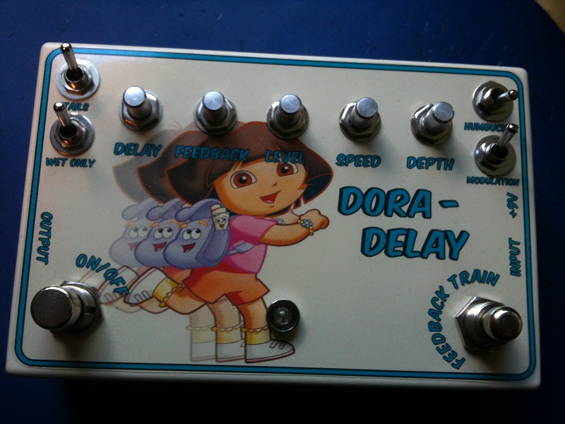
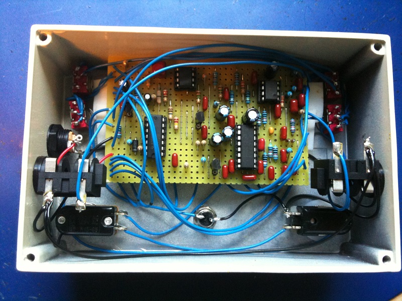
Update (06.08.2012): I’ve had this one in a box for quite a while, but haven’t gotten around to take those pictures. Here’s what my build looks like, and it is a bit untidy (also knobs still needed). Kid got to choose graphics 🙂


Hi, Joseph. Sorry to say I don’t know this circuit at any appreciable level, so I can’t really say. There might be online discussions about the circuit (not the Vero layout specifically) that might help you.
Thanks so much Harald!
I’ve built this and it’s sounding great. My only issue is LFO ticking for the modulation part of the circuit. Am I right in thinking this is coming from IC1 – TL072?
This ticking issue on other pedals seems to be solved by using a capacitor across some of the IC pins; do you have any ideas of what might help here?
Thanks again
Hi! I wonder if you could help with a bit of a basic question…
For the momentary Feedback switch, I have an SPST off-(on), but I’m struggling to work out which lug is ‘1’ and which is ‘2’.
Thanks in advance!
Hello, the list says c2 is 1uf (which is polarized) but in the vero schematic, the cap is drawn as a non-polarized one. Is there some kind of mistake or am I missing something?
Sounds like a reasonable change, john. I can’t remember that humbucker switch having any effect either, back when I built this. Thanks for letting the rest of us know.
Just got finished, another really nice effect.
I made some changes I think other might find usefull too. since the humbucker switch didn’t reduce the distortion on my guitar I’ve followed an advice to replace the two 47k resistors with 22k ones, this finally killed the destortion and made the switch obsolete.
I do not need the feedback stomp switch in my style of playing, so I’ve soldered the wires of that switch to the bypass switch. This way I can “dub in” delays by holding down the momentary footswitch.
Thanks for the reply anyway. since it’s not true bypass, I think it’s just weird that the clean signal passes through when turned on only.
Hi martin,
Unfortunately there’s little I can do except suggest you check out the debugging section for some tips. The problem could be a hundred different things 😐 Most of all I suggest going over everything with a careful eye.
I hope you’re able to sort it out.
Hi,
I just finished this build an ran into some troubles.
When not bypassed I get the clean signal mixed with the wet signal, kind of as it should be. The overall signal is just really dark sounding, both clean and wet signal. Would be a secondary issue but maybe it has something to do with my main problem:
When bypassed there is no signal at all.
The LED keeps on flashing. I used an SPST as bypass switch, would be hard to mess up the wiring on that one. I also added the clean signal kill mod. when I tap on the connections of the corresponding switch there’s some noise to be heard, in bypass on an off. Other than that it’s just dead. When I switch into bypass the tails can still be heard for a couple of seconds. After that, silence.
Any idea where the clean signal might take a wrong turn? Kind of clueless at this point.
Cheers, Martin
That would be a CD4066, typically.
Hi. What version/number is the 4066 IC?
Not today, unfortunately. But I do plan on making a tap-tempo chip that does work with this kind of delay. No timeline yet.
Hey Harald, is it possible to add a tap tempo control in this circuit?
Hi Facundo,
You can use a 3PDT. Just leave all the extra lugs unconnected.
Hi Harald! I know you told george to skip 3pdt and use a spdt, but i would very pleased if you could tell me how to wire this boy with 3pdt, since I live in Argentina and unfortunately here we don’t have an spdt stomp switch… Thanks!
Sorry to hear that, George. Unfortunately there’s very little I can do other than to encourage you to keep debugging. You will solve it if you keep at it, and even if you don’t you’re still left with valuable experience and an increased knowledge.
Thanks for the help but still nothing atleast the signal goes thru it but the effect does not sound only the level knob works an the dry switch when i activate it the signal dies
George, it’s actually easier than that.
You don’t need a 3PDT switch, you only need an SPDT onbe, or even an SPST. (Keep in mind the sheer number of controls makes for quite a few wires anyway, but the on/off, input/output wiring is pretty easy).
You need to wire the SPST off/on switch lug #1 to “Bypass SW 1” on the board, and lug #2 goes to ground. Input goes straight from the input jack tip to the board, and same with output (straight to the output jack tip).
Hope that helps!
Hey harald ive built this pedal but i need some help with the wiring can you tell me where i should put each cable on the 3pdt swith? I tried the buffered wiring but i dont know wich one is bypass output and effect output! Made several pedals of this page but this one is like the harder
Hi John S,
I have to admit I know nothing about the taptation kit and can’t really give you a good answer. But given that the vero circuit should be identical to the PCB circuit I can’t see why it shouldn’t. You might have to take into account that components may be labeled a bit differently and located at different places compared to the PCB if you’re following some kind of documentation.
I would assume that since this is a PT2399 based delay that it can be used with a Taptation kit. Do you know how you would you wire that kit into this pedal?
I’d stick with a power supply regardless, since these effects tend to eat batteries quite fast anyway.
The humbucker switch is supposed to remedy potential distortion issues when feeding the effect with too large a signal (like the difference between a single coil and a humbucker). I didn’t like it too much eaither and would probably leave it out should I build this again.
Hi Harald,
I just noticed two more things:
I’ve got the same problem that Daniel described. When I power the effect with a 9v battery the Mod section doesn’t work. With a power supply it works fine. The battery wasn’t empty, I tried it with a fresh one. Also when I use the mod with a power supply you can hear a clicking noise with the rhythm of the mod speed.
Also what is the humbucker switch exactly for? I can’t notice any difference when I switch it.
Thank you for your help!
Niko
Yeah, it worked, thank you!
Niko, the LED resistor is going to be R4 (10k) in the layout.
Hey Harald,
I’ve just build the echo base and it sounds great! I’ve got one question tho:
I used a rainbow led (needs 3.8V) and it only gets about 2V and is very dim.
I can’t find the right led resistor in the layout, could you help me?
thanks!
Niko
Yes, it’s infinite feedback that gets real loud quite fast.
Hi Harald!
Just an information…
What does the feedback train do?
Is it a sort of infinite feedback?
Thanks!
I’ve heard about people having issues with some PT2399s, but I’ve yet to encounter the problem myself. Have you verified the voltage regulator is working correctly and it’s getting +5v? Other than this I can only suggest trying another few chips, maybe from a different batch?
Hi Harald,
The EchoBase works very well but sometimes, when I start the pedal, I have to unplug the power cause the PT2399 gets locked. Or at least I guess so. The pedal goes on but there’s no delay.
I’ve tried to change the i.c. but nothing changes and they all worked in other projects without any problem.
Any idea what the problem could be?
Thanks
Alex
You’ll find the schematic at http://www.musicpcb.com under “documentation”.
thanks harald !
i start debugging, but where can i find the electronic schemes? il would help me
the 2nd thing i would like to know, would be the right voltages of the PT2399
the worst is that i m sure to be close to the solution !!
Hi mindfenris. Afraid I’m of little help. I can only suggest you start debugging. Checking the voltages is a good start. Now go back there and check for mistakes; cold solder joints, solder bridges, misplaced components, components with the wrong value, missing trace cuts or jumpers, bad/broken wires or switches etc.
i ve just finish the mine but it doesnt work, just a poor signal out of the box
a little distortion without any effect, ive changed the 7805 et check the hole but i m lost
i try to troubleshoot but i dont understand what s wrong, mu IC are supllied correctly (almost 5v)
i have no doubt about a right wiring but i dont see what wrong
if you have ideas ithank you
You can wire it true-bypass, but then you will loose the “delay tails” feature where the remaining delay repeats fade out naturally as you bypass the effect instead of abruptly being cut off. As for the caps I’m afraid I don’t have enough knowledge of the circuit to tell you, sorry.
Can I build this true bypass as is? and what caps would I change to warm up the repeats a bit?
Hi Fernando. Yes, you can use a DPDT or a 3PDT instead of the SPST. Just leave the additional lugs disconnected and you should be fine.
When it says something like “time 2, 3” it means both lugs #2 and #3 on the time pot connects to that point, but in these cases where a pot is wired like a variable resistor you can get away with only connecting the #2 lug and leave the other one disconnected.
Can i use a 3pdt or 2pdt switch instead of bypass on-off, i didn’t find a SPST on-off? If your answer is yes, how can i connect bypass and ground from board? How do i have to connect time-2,3 do i have to solder together on the pot? Thanks.
Great news, Daniel. And don’t feel bad, we’ve all done similar mistakes I’m sure 🙂
Hi Daniel. I’m afraid I don’t have the knowledge to be of much help here other than to tell you that the vero layout should indeed be correct. I and several others have built it successfully, including the modulation feature, so there’s most likely something you have overlooked.
I’m stupid. The Battery was empty. AC Adapter works with all.
Hello Harald,
I like all your layouts.
I build the Echo Base last week. It works, but the “Mod Speed” and “Mod SW” hase no function. I have checked everything. I can see no error on the vero. Do you have an idea.
Thanks!
Kind regards from Germany
Daniel
Are you sure you’ve got both the dry and the wet signal? Just a thought, but if you’ve got only the wet signal and no full-amplitude dry signal to mix it in with it might work as a volume control, and if the delay is very short you might not notice the initial dry signal not being there.
Cool, than you. It would appear that I have an issue with my build. The level pot is acting as an overall volume rather than “blend” of wet/dry. Any idea why?
It’s a “blend” control.
Hi. I’m wondering if the level control on this is a ‘volume’ control or an effect blend. Does any one know?
Hi Kim.
I don’t know the inner workings of this effect that well so I couldn’t really tell you, sorry. A good way to find out and gain some experience at the same time would be to breadboard the circuit and experiment with inserting your mod at different locations. Worst case you may have to design it in though.
Hi!
I would like to modify this with a simple bandpass filter on the feedback loop. I´m thinking an insert point somewhere, and make the filter part separately. I might even make the pedal with a jack insert point. That way I can experiment with other effects on the feedback loop.
Anyway… Could you suggest where on the vero board it would be natural to place the insert point?
(I´m sorry if the awnser is obvious! My electronic skills only contains reading schematics).
BTW: Great page!
K
I just added the other switches today except for the feedback switch, and they all work.
Though like you, I can’t hear much of a difference with the humbucker switch on or off.
Doh! You’re right, it’s ground. My mistake 😀
Thanks for reporting back, Bart. I had to go look up the layout and schematic and check the humbucker diodes, but I do believe they’re good. If I’m looking at the same components they’re seemingly connecting to C17 (4n7), but that point is actually ground which is correct.
Hey, I built this a while ago and forgot to report back till now. I decided to squeeze this layout together to save some room, which was a bad decision because it got really messy, but luckily it worked out in the end.
Some notes:
– I think I had to jumper between dry SW1 and 2 to get the dry signal through because I’m not using that switch.
– Similarly you would have to jumper between tails SW2 to either 1 or 3 if you don’t use it. I’m not sure which one enables tails.
– I checked with the schematic and there’s a mistake somewhere around the humbucker switch, which might be why it didn’t do anything? The diodes shouldn’t connect with a capacitor.
Thanks again for the layout 🙂
No worries, Jimmie. I didn’t read it that way either.
I didn’t mean that your design was bad or anything, it might have sounded like that.
Your work is amazingly appreciated!
I guess i should have gone with better parts maybe. Or maybe im comparing it to a boss DD like pedal which i shouldnt.
We’ll see if i box it or not.
Any other PT2399 delays that sounds good?
I tried the other one you have but didnt really get it to work for some reason, the delay is there but it sounds like it’s miles away.
Sorry you didn’t get it to work quite as expected. Maybe revisit this one later. It is a hard build for sure.
Yes, you can use one side of an SPDT on-on.
After a little fiddling around i decided to desolder the momentary footswitch to be able to hear what it sounds like really.
I read through the comments and realised it’s easy to get a distorted sound, i get that alot. Guess theres nothing to do about that.
And yeah, the humbuckerswitch to me dosent do that much.
I do hear a little noise kinda in the delays, might be caused by the parts used i guess, diffrent brands has diffrent qualitys.
Think pretty much everything i used was from taydaelectronics.
I guess i will leave delays and reverbs to the pros and focus on other builds.
I mean, nothing really beats the delays out there from the big brands.
But the mod things with this one is quite unique.
I just dont think all the effort and parts payd of that well :p
Build this during the weekend. I get sound out of it BUT, it’s so much modulation to it and it’s like endles.
It’s like it’s made for doing ambiances haha. Dunno if i done something wrong.
I used SPST ON-ON switches for the on-off switches, wired them at pin 1 and 2.
Isnt that the same thing as a on-off one? Also the momentary switch for the feedback dosnt work very well, tried to relocate the wiring but the same thing happens. It only gets quite if i keep it pushed in.
http://dl.dropbox.com/u/2828668/Photo%202012-04-08%2002%2056%2050.jpg
Happy you like it and I wholeheartedly agree vero is pretty great 🙂 It’s a nice alternative when you can’t bring acid into the house.
Wow, awesome stuff Harald. I like that all your layouts are veroboard. Saves a lot of trouble and cost compared to etching a pcb.
I think I’m going to try this build. Thanks!!
Not sure, you should give it a try! I’ve never looked into using effects for bass so I’m not really qualified to give an opinion. May have to change caps and modify filtering to accommodate lower frequencies?
Hi!
Would this work well for bass as well or do it need any modifications?
And if so what would these be?
/Jimmie
Hi, nice pedal, the most complicated pedal i`ve built so far but well worth the effort. Kudos to you.
Yeah Harald! You´re da Man!!! Built it on Saturday, worked immediately. Really nice sounding Pedal, and I love the “Mod” Mode!
Thanks for all vero Layouts, much appreciated!
Oh ok. I don’t know how I missed the output at i35. Thanks Harald!
Hi, Spencer.
1) I don’t know about the delay time, but I’ve seen 700ms quoted. It gets distorted at the longest delay settings, though.
2) The humbucker switch was one of many suggested mods, thought to reduce distortion when using humbuckers. Since I prefer humbuckers myself I thought I’d throw it in there, but it didn’t seem to do anything. You can ignore it and instead wire “Humbucker SW 1” directly to “Feedback 2”.
3) No, the “Output” (at i35) is the output. I may have forgotten to state that this is a buffered effect, so no true-bypass. The on/off stomp switch you normally use is the “Bypass SW”. It’s a 1-pole latching switch (either on-on or off-on) that either routes the signal through the whole circuit or just through the buffer.
Hey Harald,
Nice looking layout as usual. Three questions, 1)about how long is the delay time? 2)What’s the “humbucker switch” for? 3)The Bypass SW 1 is the circuit’s output?
Thanks
Sounds like that 7805 might very well be the problem. Have you double checked the pinout by the way? I’ve heard some of the other regulators have reverse pinouts compared to the 78L05. Here’s to hoping you can solve it!
I built this last week, and was unsuccessful. I couldn’t get a signal from it.
After spending a good few hours trying to debug it, I gave up and built the true bypass version (with a 3pdt switch instead of the 4066)as it seems simpler.
That didn’t work either!
I think the problem is that I used a 7805 regulator instead of a 78L05. I’ve read that they don’t work very well with a 9V battery
. I kept getting 7V from it, even with a decoupling capacitor.
My local maplins will have the 78L05 in stock next week so I’ll try then.
Hopefully it will work, and I’ll end up with 2 delay pedals like the Edge!
Be sure to refresh your browser and get the revision 1 layout.
Good stuff, thanks for being brave!
I’ll make one this week
I’ve built a few of your layouts and really appreciate the site
Built it tonight and it works! I’ve updated the layout with a few minor fixes. 1) “Time” and “Mod speed” pots have been re-oriented. 2) R36 (and the associated cut) has moved along with the “Feedback switch lug #2” wire (and C19 / C21 had to move a bit to make room for R36).
I’m planning on doing this one this weekend as a matter of fact. With a bit of luck I’ll be able to finish it too.
Has anyone verified this layout?
I’m looking at building it but I’m not brave enough to go first!
Just Thanks !