I actually tried three different versions of this effect (this has to be the effect pedal with the most variants by far), a “Ram’s Head”, a “Civil War” and a “Creamy Dreamer”. They all sounded about the same to me. I ended up boxing the “Creamy Dreamer” variant.


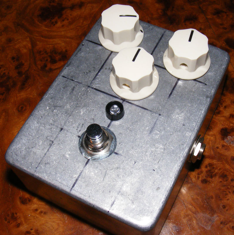
I initially intended to paint this enclosure, but it turns out I’m not really artistically inclined. In retrospect I shouldn’t have made those measurements in permanent marker. I more than made up for it by adding some cream colored knobs, though.
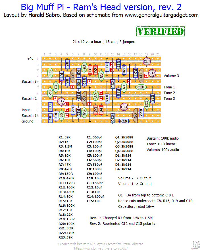
Update (15.02.2012): Benno spotted a mistake on the Ram’s Head layout where a 1M5 resistor was accidentally labeled as 1K5.


Hi Harald – what size enclosure is that, or what would you recommend for this build?
Check out the wiring section. Should be an applicable wiring diagram there.
Hello
Could you put how to connect the footswitch to the jacks and led board?
Thanks
Harald –
Your permanant marker “snafu” honestly looked like a weathered wall drawing to me. Suitable art for a muff.
Hi bob,
I can’t give you a good answer on how to add a mid control to the BMP, but I’m sure this has been addressed somewhere by someone. Try searching for BMP tone control mods, maybe on the forums (links on the right-hand side).
How would you go about adding a mid control pot to the civil war layout?
I’m guessing a mis-biased transistor, it should be really loud. It could be the transistor itself, or you could have a mistake with one of the supporting components. Check out the new debug section and start with a visual inspection.
Hi! I built the Civil War version last night and it sounds great except the volume doesn’t get very loud and right before I hit max volume it cuts out completely. i changed out the pot and it still does it. Should I check the transistors or could it be something else?
Thanks!!
Just finished the creamy dreamer. Sounds pretty cool. Has a little more noise than some of the other gain pedals I’ve made, but really sounds good, the noise is not an issue. It pretty much sounds like early 90’s pumpkins or sonic youth. I put mine in a purple box with a hot pink led, makes me chuckle on the inside. No problems, great layout. Many Thanks. So far successfully made this one, the devi ever soda meiser, d0d 250, cb heliotrope, JH compressor, Rebote 2.5, almost done with my ts-808. Sadly still can’t get my silicon fuzz face quite right, which sucks because it’s so damn simple, but I haven’t whole heartedly trouble shot it yet. Thanks for all the great layouts, this site rules!
I haven’t really looked into all the versions of the BMP and I haven’t seen a layout for the version 3 you mention, but I’ll happily add it to my list for future consideration.
hi harald,
do you know the version 3 and have you ever made a layout of this version or know any layout of this one?
it’s this: http://www.kitrae.net/music/big_muff_historyB.html#Version3
Love this one, built it last week. So smooth compared to a stock NY muff, great for Sabbath/Stoner rock sounds… thanks Harald for another great layout!
Happy to hear that 🙂
Hi again!
Thanks for the input, i totaly missed that R6, that coused the whole thing, it’s not working and sounds amazing!
Thanks for your help and fantastic schemes!
Thanks for the input, will try this tonight and see if i get it to life.
As for the sockets i were just cheap, i used them in the OCD build of yours but were short on them for this.
Will use em next time! As you said, the R6 looks misplaced. Will be interesting to try it.
Thanks again!
Jimmie, I believe R6 is misplaced on your build. And make sure R4/C12 doesn’t short on the component side, they look like they might. Otherwise it looks OK (I can’t tell whether there are any shorts etc. on the track side).
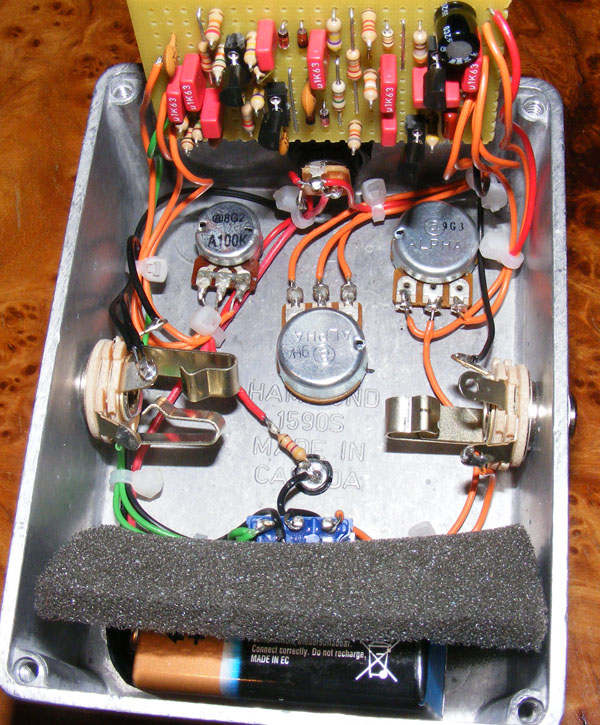
If you’re going to do more builds in the future I strongly recommend using sockets for your transistors and ICs as it’ll save you a lot of headache when you end up placing them the wrong way or your particular transistor has a different pinout from the layout etc.
Hi, Jimmie. No, ceramics or polys shouldn’t make any difference except -maybe- in the sound, but then only very slightly.
I’ll have a look at the pictures you posted soon as I get around to it.
hi.
just made the creamy version and wired it up with jacks and studd, i have sound when bypassed but when i put on the fuzz i hear nothing, i can just hear a quiet humming sound, it changes when turning tone knob, you can hear that the tone is working, also the volume is working etc. but all that comes out is this very quiet humming.
this is the vero: http://dl.dropbox.com/u/2828668/Photo%202011-12-11%2016%2037%2007.jpg
and under the vero: http://dl.dropbox.com/u/2828668/Photo%202011-12-11%2016%2037%2031.jpg
maybe you can see something that is way wrong, i noticed you used ceramic caps, does this affect the build that i got polyesters all over it? mught this be the failure of it? i checked for the soldering as well and couldent find any bad ones.
thanks in advance!
You are welcome, Anto.
just finished your muff! it sounds good!!
thank you so much herald for the help and the layout!!
Sorry Anto, I missed your last question.
You’re right, the D1 and D2 diodes in the photo have switched places compared to the vero layout, but this has no consequence at all. In this case both the layout and the actual photo is correct. And the same applies to D3 and D4 as well.
..could you help me?
Thanks a lot Herald!
But now I’m realizing that dioded D1 and D2 aren’t in the same way too…
What’s their right position?
I’m sorry for the many questions
Hi, Anto. I had to go back and have a look, but I realize what you’re getting at now. The vero is correct.
What isn’t really made clear in the picture is that I was using ceramic caps with a 5mm spacing, and I bent one of the legs back in to fit the 2.5mm span.
Hi, while I was building your big muff creamy dreamer I realized there is a problem between the vero layout and the photo “build” about ceramic caps C1, C6 and C7: they aren’t in the same way…..
What’s their right position on the vero board?
I thank you in advance!
I built your Civil War version, sounds great!
http://www.buildyourownclone.com/board/viewtopic.php?f=8&t=27966
Hi, GuineaFowl. Thanks for your input.
Acetone, of course… I tried using a pencil rubber with little effect. But at this time I can’t be bothered to undo the jacks, switch and knobs. As long as it works I’m happy.
I actually received another quite useful tip from a member of the diystompboxes forum. By covering the enclosure in masking tape you can make all the measurements you want, and it even helps the drill bits stay where you initially want them. This also makes it easy measuring painted enclosures.
Hi 🙂 I use permanent marker on my die cast aluminium enclosures to mock up designs and lay things out too. It comes off really easily with a tiny bit of acetone on a tissue or cotton pad. I use my girlfriend’s nail polish remover.
I’ve just finished building a black russian muff variant and found your site while browsing google images for others who have built muffs. Funny enough mine also has all WIMA capacitors and is a stripboard layout with socketed transistors.