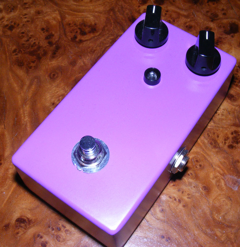
I discovered smallbear sells pre-colored enclosures! Even though I’m all about functionality I have to admit it’s pretty neat. I always wanted to play with an octave fuzz effect, and I guess the classic Tycobrahe Octavia would be a good place to start.

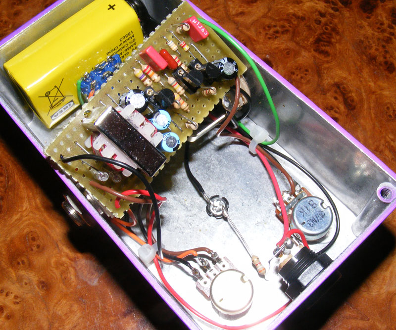
I had to drill slightly larger holes in the vero board to accommodate the wider transformer chassis pins.
Update (25.05.2012): Re-oriented C5 which was sitting the wrong way. Thanks to Marcus for spotting this one.


No, NPN is not negative ground. NPN signifies one of two different types of bipolar junction transistors (the other one being PNP), neither of which has a specific requirement when it comes to the polarity of the DC. Whether the effect is negative or positive ground comes down to design more than anything else. And this particular effect is negative ground (as is most effects these days).
is NPN negative ground?
thx
I used the nte cross reference transistor for q1, maybe I should have measured the hfe first. This thing is FUZZY. I like it that way, tho. Going to see if I can add the octave switch in.thanks for the circuit layout.
Thanks for the feedback and mods, Andrea 🙂
Excellent layout!
I’ve found the optimum with a 2N5087 on Q1 (hfe 515), a 2N5088 on Q2 (hfe 530) and a 2N3904 on Q3 (hfe 210): sweet and balanced octaves with plenty of harmonics and overtones.
I’ve also lightly modified the layout for allowing a switch (or a 3PDT footswitch) for including the possibility of choosing between octave and standard fuzz:
1) use a 25 columns veroboard instead of the actual 22
2) solder D2 on 24 E-H instead of the actual 21 E-H mantaining the same orientation
3) broke the row H on 22
4) run two wires from H-21 and H-23 – on the two sides of the break
5) solder the flying ends of the wires on the center lug and on one of the lateral lugs of the SPDT; for the 3PDT footswitch, remember that it’s simply an ensemble of three SPDT put together side by side… so you’ve just to choose one of the columns and wire it as you would do with a SPDT.
When the two wires are switched in connection you will got the octave mode; when not you will obtain a smooth, rich vintage fuzz with great sustain and a full and rounded body 🙂
As usual… thanks, Harald, you are great!!
Your transformer should have one side labeled with a “P” or something similar to indicate the primary side. The other side is the secondary.
For this build you don’t need the center tap on the secondary, but all other leads should be soldered according to the layout (you probably have to bend the outer leads somewhat to make it fit the holes on the vero).
Hi Harald,
can you tell me,
in which direction the transformer is placed?
Which Contacts of the transformer have to be cut an which have to be soldered? (or should all be soldered)?
I’m new in the field of transformers…:(
Thanks, Alan. Much appreciated 🙂
Built this pedal and really pleased with the sound. It was a tight squeeze. I had to add a few rows to the vero as my transformer was a little larger. This was also the first pedal that I painted and labeled, it turned out very well. Thanks Harald for the great layouts. Donation on it’s way.