You requested it and here it is, a vero layout for the G2D Cream Tone. I don’t know what this effect sounds like and I haven’t verified the layout.
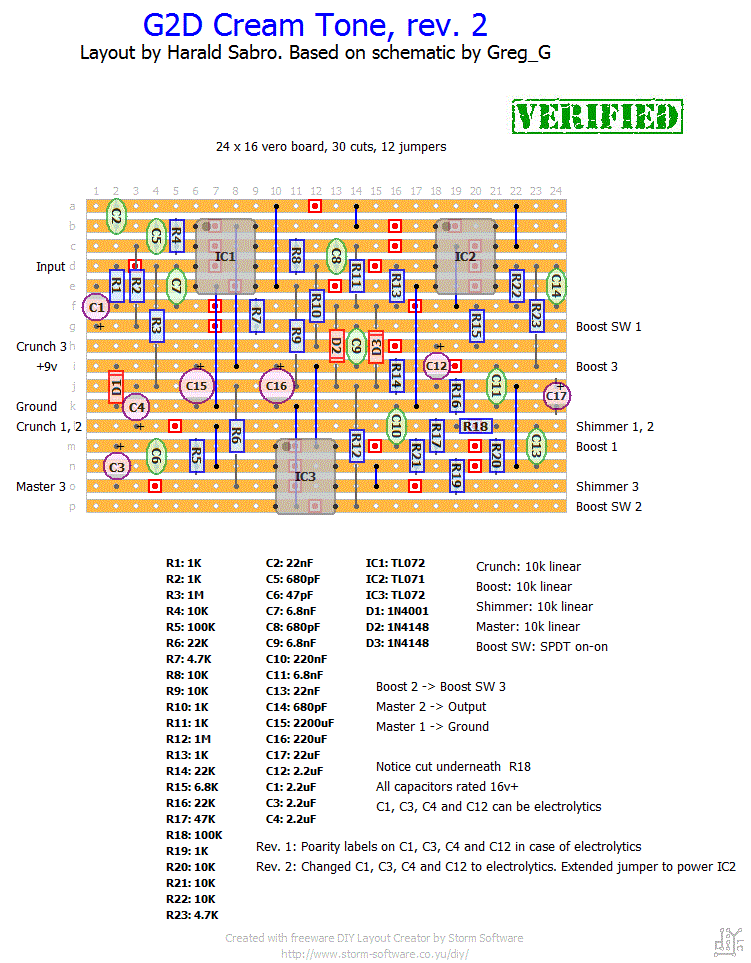
Update (21.02.2011): Added polarity labeling to some of the larger capacitors.
Update (24.08.2011): Changed a few large caps to electrolytic type and fixed a jumper mistake on IC2 VCC+. Verified as working.


If they’re rated higher than 16V it shouldn’t be a problem. Don’t use lower ones unless you can read the schematic and know what DC voltages each one operates on.
Brand of electrolytics shouldn’t matter much and they’re all of poor tolerance. I don’t quite understand what you mean by the revisions, but as it stands now the rev.2 layout should be good as you see it. No changes needed; you don’t apply the rev. notes at the bottom, those are only there for historical reference.
You have noticed that IC2 is supposed to be a TL071 and not a TL072?
If you’re stuck check out the “debugging” section.
capacitors that I have provided are not all at 16v. do you think that might work but for this?
I ended but the master volume is low and the boost works badly. I double checked everything and it all seems ok.
What you electrolytic capacitors have used over, ceramic or polyester? and what tolerances?
the rev.2 regarding IC2 is marked on the diagram that you did? . I did as it is written on the diagram, imagine that you have it written on the diagram.
I also reversed for error by IC2 with IC1 feeding circuit (then I put in the right location), and you might be broken?
when the boost is turned on which contact must be closed boostsw2/boostsw3, this is right?
Can you help me for what I can do from there?
sorry for my english …. not the best!
Any specific reason why you want this wired as a buffered output? The reason you can’t find the circuit bypass output is because the circuit itself hasn’t been designed for buffered wiring. Go with the regular true-bypass wiring instead.
I’m sorry, one more question. which is the “circuit bypass output” as shown in the wiring section “buffered wiring (no battery)”, in the scheme of creamtone?
Wire it all up according to the true-bypass diagram. Now, in addition you’ve got a boost switch which is entirely separate. You have a lot of choices in how you want to wire it, but a stomp switch is probably the best choice. You can use a single pole, double pole or even a triple pole (the usual blue 3PDT stomp switches), but you actually only need one of the poles (two if you’re adding an indication LED for the boost switch).
ok I get it ….. so I have to use the foot switches as shown in figure 1 (no battery), but I have two foot switches 1 to 6, then I have to change them with those from 1 to 9?
I’m not sure I follow you all the way, but there’s one switch explicitly mentioned in the layout; the boost switch. And then there’s your regular true-bypass switch that’s not mentioned in the layout (look up the wiring diagram in the “wiring” section).
hello I do not understand one thing ….. the creamtone has two footswitch for an overdrive and one for the boost, if I understand it in this scheme there is only one footswitch …..
and then the footswitch are switch or switchman?
Try increasing R22 (10K). The larger you make it the more gain (and distortion) you’ll get out of the boost stage.
Hi Harald. Just a little question: how can i increase the boost volume? Change any components?
Andrew, I haven’t tried this circuit at all so these are only non-educated guesses. Try changing C2 (22n) with something larger (a 100n should move the lower cut-off frequency from ~700Hz to ~150Hz). I’m also pretty sure you can make a few adjustments in the “shimmer” section; maybe try lowering R21 from 10k to 1k (more bass frequencies passed to the next gain stage) or lowering R17 (47k) to something lower (increases the gain of the given lower frequencies, I think). It would probably be easier to replace those resistors with wires and attach pots wired as variable resistors so you can experiment freely without doing a lot of soldering back and forth.
Hey Harald (or anyone else), Do you have any ideas about how to increase the bass response of this circuit? How would I go about doing that mod? Thanks!
Hi hohabro. You’re not going to find the output on the board itself, but there should be a list of additional off-board connections in the lower right-hand part of the layout, and one of these connections is a wire from lug #2 on the volume pot.
Hi, thanks for the layout. I have tried building this, but have a (noob) question. where is the ‘output’ on the veroboard layout? any help appreciated (this is my first attempt at diy)
Hi James. I haven’t built this myself so I can’t give you any voltage readings, but I can make a fair guess as to what you should see.
On IC 1 & 3 you should see +9v on pin 8 and 0 on pin 4, and the rest of the pins (1, 2, 3, 5, 6, 7) should be at approx. half voltage; or +4.5v.
Could it be that the boost switch is failing and you’re only hearing a tiny portion of the signal bleeding through? Seeing that it used to work fine something has obviously failed, and those cheap mechanical switches do so quite often. You could give it a quick probing with your DMM.
My boost used to work, now it almost completely cuts the volume but you can still hear it very faintly. I checked all the ics and wiring. The boost is obviously switching on, so anybody with an idea for my problem? Correct voltages would be helpful. Thanks. PS Sounded great when it functioned correctly or without boost
Hi Andrew. To be honest I have very little knowledge of this specific circuit, but this is a new symptom to me. I don’t know what the cause might be, so I can only encourage you to do some solid, nit-picky debugging. Double and triple check all component placements, component values, cuts (location and whether they’re proper cuts), jumpers, look for solder bridges etc. Also double check your wiring to make sure that’s not the cause.
Hope you can figure it out.
Hey Harold, I built this circuit up and it sounds great but the sound is pulsing along with the LED which is lit but lightly pulses in about 1 second intervals. Its almost like a power buildup and drain that is pulsing but I really have no idea what it is. Could this be a bad capacitor or otherwise? I switched out all of the IC’s so its definitely not the IC’s. Any help is appreciated. Thanks.
I guess you can argue that the shimmer pot controls the tone, but really this is how the original unit comes so it is by design.
hi! i wonder why there is no tone-control. the circuit sounds very nice (creamy:) but also very dark
Tom
Now everything is clear!
I’ve made the measurement with the multimeter, and i’ve found the “common”!
I’m going to wire!
Harald, THANK YOU SO MUCH!!!
🙂
Hi GX. Hard to tell from the picture, but should be easy enough to figure out with a multimeter. Try measuring continuity in both switch settings. One of the lugs is connected in both cases and that’s your common lug. Label this one #2. The other two lugs can be either #1 or #3. It doesn’t matter.
Hi Harald, just another question:
i don’t know haw to give the right numbers to the pins of my SPDT swith.
I’ve got the spdt that has 2 pins from one side of the switch, and 1 pin on the other side.
Which of these is the pin number one? Which the number two and the number 3?
This is my SPDT switch:
http://www.tube-town.net/ttstore/images/product_images/original_images/3697_0.jpg
Thank you so much!
I use DIY layout creator v1 made by a fellow enthusiast. You’ll find a link to the site on the right hand side; DIY-Fever.
You’re right!
It works great!!
Thanks a lot!
Just the last question: what’s the name of the software you use to commute the schematic draw to veroboard layout?
i’m trying to begin to convert a lot of schematics into a veroboard layout.
Thank you so much!
Have a look at the “Schematics & drawings” page at the different wiring schemes. This might give you an idea of how to do it.
I’m guessing that the first 3PDT is wired like a regular true bypass switch, and the second switch toggles either of the other two LEDs based on whether the “Solo”/boost stage is engaged or not. Since the boost switch only uses one pole for switching you can get away with using a DPDT here. Wire the center lug on the second pole to ground and the cathode of each LED to opposite outer lugs. Now wire each LEDs anode to +v via LED resistors and you’re good to go.
Thanks for your answer Harald. Yes, i’m speaking about the 3 led that the original version of CreamTone has, as you can see at the minute 2:22 of this video:
http://www.youtube.com/watch?v=gy79nPanDsQ
I’d like to put the same sequenze of led in my clone, using your favolouse layout.
(Sorry for my english, that is’n so good!)
Thaks everybody!
I’m not sure what you’re referring to when you say “3 LEDs”. Do you mean the two indicator LEDs (one for on/off and one for boost)? If so have a look in the “schematics & drawings” section for various offboard wirings and such.
Sorry, just one question: where can i put the 3 LEDS?
There are no informations about this on the layout…
Thanks so much!
I think I found your problem. I reviewed the layout tonight and found a mistake that would probably result in the problems you’re having. The upper right jumper supplying IC2 with power was incorrectly connected to pin 8, while a TL071 use pin 7 as VCC+. I fixed the jumper and built the circuit successfully.
Sorry for having to wait so long. Layout updated and verified. Hope this solves your problem.
PS! Incidentally C9 can be connected to either v+ or ground with no difference.
The suggested correction was to tie C9 on the layout to ground instead of v+. I can’t confirm whether this will make the unit work, though.
Thanks for the project, already built and seem very nice. However still have the problem with boost switch. I have tried to follow that link on freestompboxes.org but the like didn’t work. Could you please post what an error on the schematic or how to correct it. However, The sound is very very nice.
Thank you very much Harald
Did you run into the same issues as Aboy or does your “boost” work as expected?
Hello again! the layout above is working! awesome sounding pedals really great for blues.. Now i wish to see G2D Custom Overdrive! HEhehe…
Thanks for the info and link Harald, much appreciated!
Aboy and Snowy, if you have a look at the discussion on the “Schematics & drawings” page I recently discussed this layout with Mike and he thought there might be an error in the schematic: http://www.freestompboxes.org/viewtopic.php?f=7&t=11957. Might be worth looking into.
Thanks for this layout.
Aboy, did you figure out the issue with your Boost switch?
Is the actual schematic available somewhere?
ok DONE! it seems to work fine. But the boost switch doesnt work, nt sure why everything wired up accordingly.
Anyway, the od is extremely nice! I dare to say that it is the best bluesy od i ever played in my entire years. oh yes it can do rock very well too.
This will be in my pedalboard.
Will do.
hi im about to build this, emm could you label the polarity of those 2.2uf?
you can cahnge it also to 100 – 47 uF and wont change anything.
again thanks for the layout
No, according to the schematic it’s 2200uF, but this is the power section and I’m sure you can omit it and still have a working effect.
Thanks harald for for ur kind work. Is C15 220uF??
I be sure to build this and report back.