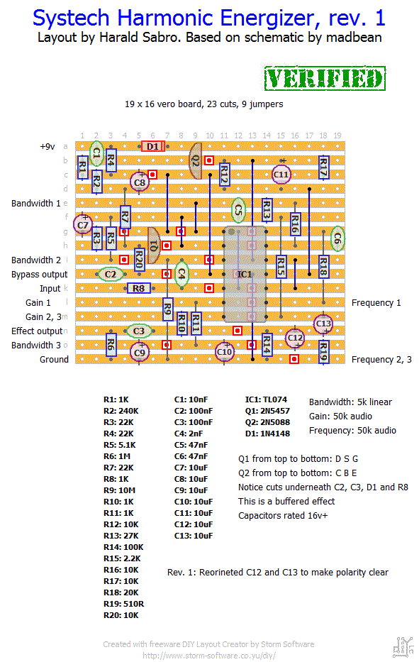
I was reading discussions about various vintage effects on freestompboxes.org when I stumbled upon a thread about the Systech Harmonic Energizer. I knew I had heard the name before, but couldn’t recall where. After reading the thread it dawned on me that I had seen it at madbeanpedals. It’s one the great PCB projects he’s got on his site. If you like PCBs I encourage you to order one of his. If you’d rather make your own vero board here’s a layout for it.
Update (17.10.2010): Added missing resistor between Q1 source and C2. Thanks dune2k for spotting this.


Nice layout. Does anybody know, how the additional switches in this version work? Would be great to include them.
https://youtu.be/lhNFPsbv2Lk
Hi GP,
Your true-bypass wiring scheme should be OK. Yes, use the input and effect output as you would a normal true-bypass wiring, and ignore/leave out the buffered bypass.
Hello Harald!
Two questions:
-How would one go about making this an unbuffered effect?
-If I were to wire this up like a normal true bypass effect (do my own bypassing on the footswitch), would I just wire the effect output and ignore the bypass output? I have a favorite wiring scheme and would like to stick to it as much as possible.
I’m guessing you’re looking at an updated schematic as I don’t have any 47u on the one I based this on. It shouldn’t matter much though.
As for the 18k/20k, if you like the way it sounds now I wouldn’t bother since the difference, when component variance etc. are taken into account, is probably going to be slim to none.
And finally, any TL074 will do fine. The postfix on most ICs can be ignored (there are exceptions though).
While reviewing the madbean scheme, I notice a 47uF cap on the 9v to GND. Omiited on this layout, is it not necessary? Also, on R18, I opted for 18K, but am thinking of treeing two 10k’s to get to 20. Finally, I cannot find any info on differences between TL074 (plain) and TL074CN. Does it matter? Thoughts? Thanks.
Thanks for another great vero Harald. Just finished my build, everything works…now that I swapped out an incorrect 150R for a correct 10M (R9), both have the same 5-band markings except the wrong direction, d’oh! Too late to crank it up, but will tomorrow.
best regards,
You’ll need a DPDT foot switch (or a 3PDT, but one pole will be wasted). One pole will be used to control the effect state and one will be used for the indicator LED.
Wire the center lug of the effect pole to the output jack, then wire the “effect output” to one of the outside lugs and the “bypass output” to the other one.
Wire the center lug of the LED pole to ground, then wire the lug on the same side as the “effect output” to your LED’s cathode (-). The other leg on your LED (anode) goes via a resistor (1k-10k ish) to your power source, typically DC jack.
And the “Input” on the circuit board is wired directly to the input jack.
Hope that helps.
Effect output and bypass output? Does one go to the footswitch and one go to the tip of the jack? How is that wired?
Excellent, Nick! I’ll update the layout page right away. Thanks.
I have built this layout. Consider it verified!