I’m working on a Baja Trembulator, a tremolo circuit Bajaman from freestompboxes have designed based on the Demeter tremolo. Since I haven’t gotten into etching my own PCBs yet I thought I’d do a vero layout and try it out. I haven’t actually created the circuit yet, but I believe the layout is finished. Just waiting for the parts to arrive in the mail now…

Update: Built the circuit last night and discovered a mistake on the layout. I had forgotten a cut between C3 and C4, and both pots were reversed, all of which has been corrected now. Layout hereby verified.
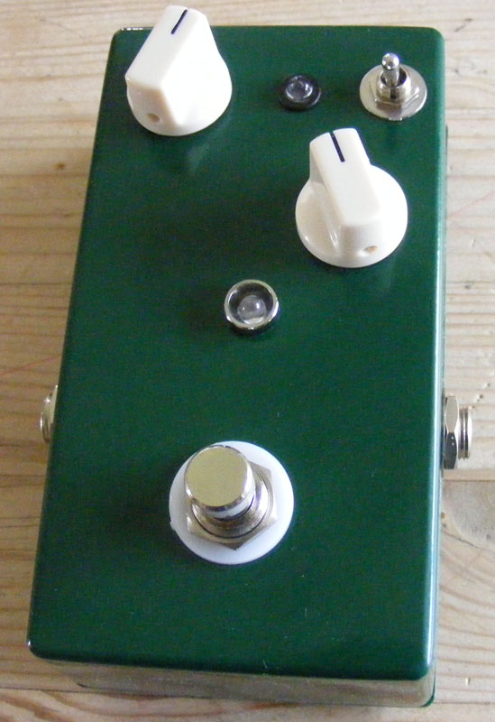
Update (07.06.2010): Finished up my Baja Trembulator build yesterday and what a beauty. It sounds great too.
And yes, I accidentally soldered the IC3 socket the wrong way.
Update (20.10.2011): Fixed dead picture links.
Update (10.11.2011): I accidentally attached the wrong layout (wonder how long that one’s been up). This is now fixed, but you may have to hit refresh.


You should get sound through C5 and to the Depth pot lug #1 (and #2 which is the output). On the depth pot side of C5 you should read a resistance to ground that varies with the LFO, somewhere in the 20k-100k region I think. Alternately, if you disconnect the LDR you should only have the 100k to ground (and sound).
Great news, I’ve managed to get it oscillating, however, I just get the oscillation through the output at the moment.
IC readings are now:
IC1 : 0.15 4.32 2.63 0 0.15 4.3 8.7 0
IC2 : 8~1 5~3 6~3 0 6~3 4~2.5 5~3 8.7
IC3 : 5~3 6~2.5 5~3.5 0 0~1.5 7~1 8.7 0
where ~ denotes an oscillating voltage.
I have used an audio probe to trace the signal from input to pin 3 of IC 1 and out of pin 6. This then goes into the pin 2 input via R6. The signal enters R13, but thats where i seem to lose it.
Should it travel though C5 to the depth pot? Or is it grounded through C5 and R11?
Thank you very much for your help so far. I have no idea why this project is causing me so many issues compared to my previous pedals.
Sam,
The last row on the vero (left side) that connects to IC2 pins #3 and #5 is the bias voltage for the LFO. It’s set to approx. +v/2 by R5 and R10, and I believe it should read somewhere around +4 – +4.5V, so something here is still wrong. Since the bias is low that also explains the low reading on several of the other pins. I think there might be another small mistake around there somewhere.
And sorry for the not-so-quick response.
Thanks for the quick response. I found I’d missed a cut, now I get signal coming through, but with no effect and a high pitched oscillation that seems to originate in IC1. I’ve tried changing the IC, but it stays the same. The new measurements are as follows:
IC1 same as before ± 0.1v
IC2: 2.34 2.37 2.39 0 2.39 4.69 5.69 8.16
IC3: 5.69 2.42 5.68 0 1.34 2.39 8.16 0
I’ve also measured the VTL in at 1.56V. I’ve remeasured all the resistors and replaced the parallel caps I made with the correct value single caps. Obviously the fact pin 6 on IC3 is static means there is something still wrong.
Cheers
Sam
Sam, without having checked the voltages on my own build some of these readings seem wrong. IC1 looks reasonable, but I’m not so sure about the other two. Check out the debugging section for some ideas; I’d start looking for some mistake in the lower half of the vero.
Hi Harald, Seasons Greetings. Sorry the formatting all came out when I submitted, I had tabbed them.
IC1 : 0.14 4.05 3.03 0 0.14 4.05 8.11 0
IC2 : 6.49 5* 6.39 0 6.39 0 0 8.11
IC3 : 5.68 8.11 5.69 0 0 1.68 8.11 0
Many Thanks
Sam
Sam, I’m having a bit of trouble deciphering your voltage readings, but they look quite a bit off regardless. Your highest voltage is 7.15? That would imply a battery/power source of roughly +7.7V; as a start I’d get a fresh battery and redo the voltage readings.
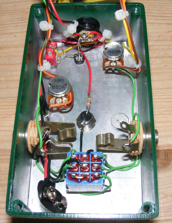
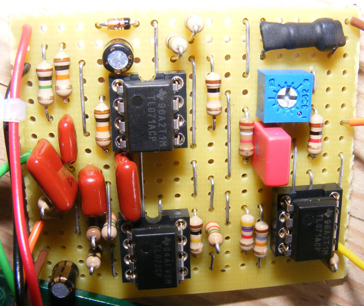
I’ve taken a front and back pic. The I’m using a VTL5c1 (checked it hasn’t blown) and TL07x chips. The only ‘fudge’ I made was with the caps and resistors near IC2, I’ve done some summing of components (series for resistors, parallel for caps). https://dl.dropboxusercontent.com/u/7620516/Baja%201.jpg https://dl.dropboxusercontent.com/u/7620516/Baja%202.jpg
The board looks pretty shabby, but I’ve been over it with a multimeter and can’t for the life of me work out what’s wrong. This is my 6th build (first trem) and the only one thats caused issues.
Many Thanks.
Sam
Just as a follow up: I’ve knifed all the gaps and tried changing all the chips to see if one was dead, but still nothing. I’ve taken the following measurements of the chips:
IC1 IC 2 IC3
0.12 0 1.47 7.16 0.08 0
3.58 7.14 3.57 0.08 7.15 7.15
3.0* 3.58 5.65 0 0.08 5.65
0 0.12 0 5.65 0 0.1
* drops from about 3 to 2 when I measure it.
continued below (send buttons disappear for a long message :-S)
Hi Harald, I’ve just started debugging this circuit, I was wondering if you had a record of the ic voltages to expect? Or perhaps an audio path I can prove? Kind regards, sam.
Nice one, Moritz. I happen to love the trembulator too 🙂
Hey Harald, I wanted to say thanks for this awesome site. I just finished this one, it’s the second of your layouts I tried and I’m so happy with it. Really cool stuff! Greetings from Berlin.
http://instagram.com/p/cGzNAHhytv
Excellent suggestion, Kimster.
Hi! This was a really nice build and it sounds great. However I think the rate is a little narrow, you can´t make it really slow or really fast so I changed the rate pot to a 500k rev log (I think the demeter uses a 500k) and changed the R2 resistor to a lower value (5.1K I think). Now I can get the rate much slower and faster and the rev log pot gives a smooth range. Thanks again for your great site Harald!
Thanks, I tossed in a b50k I had laying about and it works perfect for make up gain. Thanks!
You can swap out R6 for a larger value to increase the gain. Or maybe replace it with a pot, say 100k, for a variable gain control.
Harald,
Is there any way to mod this circuit for more volume for the effect? When the depth is at zero (full dry signal) it is at unity volume with bypass, but when I dial it 100% depth (all tremolo) the volume is quite lower than when bypassed.
There were some mods mentioned on the freestomboxes forum, but they were for a different layout with different op-amps.
It’s a lovely sounding tremolo, but due to the volume difference I haven’t been using it on my pedalboard much.
Do you think I would get more effect volume if I used the original op-amps (I used TL071/TL072)?
– Thanks!
That’s a very cool suggestion. I’ll make a note of it.
Hi.
Revision.
Like the Supatrem, you can put a 2pdt footswicth (or a spdt) to bypass the VR1. This just makes the VR1 likes if it was 0. So the led of the optocoupler gets maximum bright and you get a almast square signal, It’s the hard/soft footswitch of the fulltone supatrem.
built the entire layout.
no oscillation from the led; well…it is really barely noticeable (even with the 10k trim)
What could be the origin of the prob?
Thanks!
Built this last weekend, built the entire board before realizing I had a printout of the old layout with the mistakes, oops. So I changed the components that needed moving, cut the extra cut and it works perfect… nice and smooth. I changed the resistor going to the rate pot from 10k to 5.1k to get a little more speed. I may put it on a switch with a 1k to get crazy fast if needed. Thanks for the cool layout!
Great, and thanks again for catching the layout mistake.
Just built this today, worked first time (always a relief!), many thanks for the great layout.
Excellent, many thanks!
Hi, Nocentelli. Oops, good catch. I did a site update a couple weeks ago and must have used the wrong layout. Please ignore this one, I’ll update to the correct version once I get the chance tonight.
Hi, really enjoy your vero layouts, have built several so far. I’m looking forward to building this at the weekend, but I’m just unsure about one thing – The layout appears to suggest the depth pot lug 2 should be connected to G20 (i.e pin 5 of IC1) as well as the output: Is this right? I doesn’t seem to match any trembulator variant schematici can find. Thanks again for all the layouts.
Thanks, both of you.
Greetings, I enjoy your blog. This is a cool site and I wanted to post a little note to let you know, good job! Thanks Louis
Louis Vuitton
louis vuitton
great post, thanks. theres great stuff in this site